Combined drainage device

A drainage device and combined technology, applied in water supply devices, indoor sanitary piping devices, buildings, etc., can solve problems such as poor drainage, sawing off, splashing on the buttocks, etc., and achieve the effect of adjustable direction.

Inactive Publication Date: 2010-12-01
张超
View PDF5 Cites 12 Cited by
  • Summary
  • Abstract
  • Description
  • Claims
  • Application Information

AI Technical Summary

Problems solved by technology

[0002] my country's commercial housing construction is accelerating. In the current construction industry, according to the national construction design specifications, kitchen and bathroom drainage pipes are the corresponding interfaces of each sanitary ware. An independent water trap, water sealing device, and toilet seat must be installed. Squatting toilets must be equipped with water traps and water sealing devices, but the water in the water sealing device is too close to the human body and the ground, so it is easy to volatilize and become dirty after deterioration. The dirty water in the water sealing device often splashes on the buttocks when users use it , very unhygienic, and the installation process is complicated, with many bends, easy to block and difficult to dredge, poor drainage, and inconvenient maintenance. Construction companies usually format and install traps and water seal devices in the pipeline in the same way. With the improvement of living standards , the decoration standard continues to improve, it cannot meet the needs of users for personalized and humanized decoration
The user usually needs to adjust the distance and direction of the sanitary ware when decorating. This will saw off and abolish the original drainage branch pipe, and install it separately according to the actual situation, which will cause a lot of waste. Retrofitting and installation in an unprofessional situation may also cause water leakage. Hidden danger, this invention is to solve the above technical problems

Method used


Image

  • Combined drainage device
  • Combined drainage device
  • Combined drainage device

Examples


Embodiment Construction

[0035] The present invention will be further described below in conjunction with the accompanying drawings and specific embodiments.

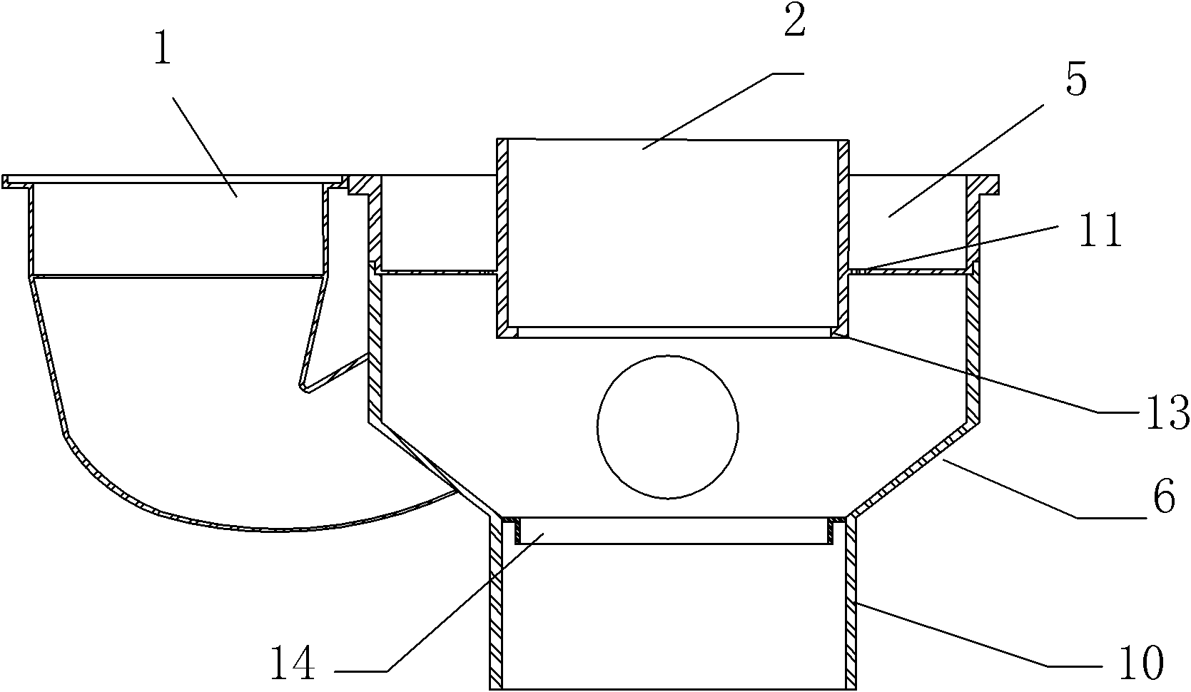
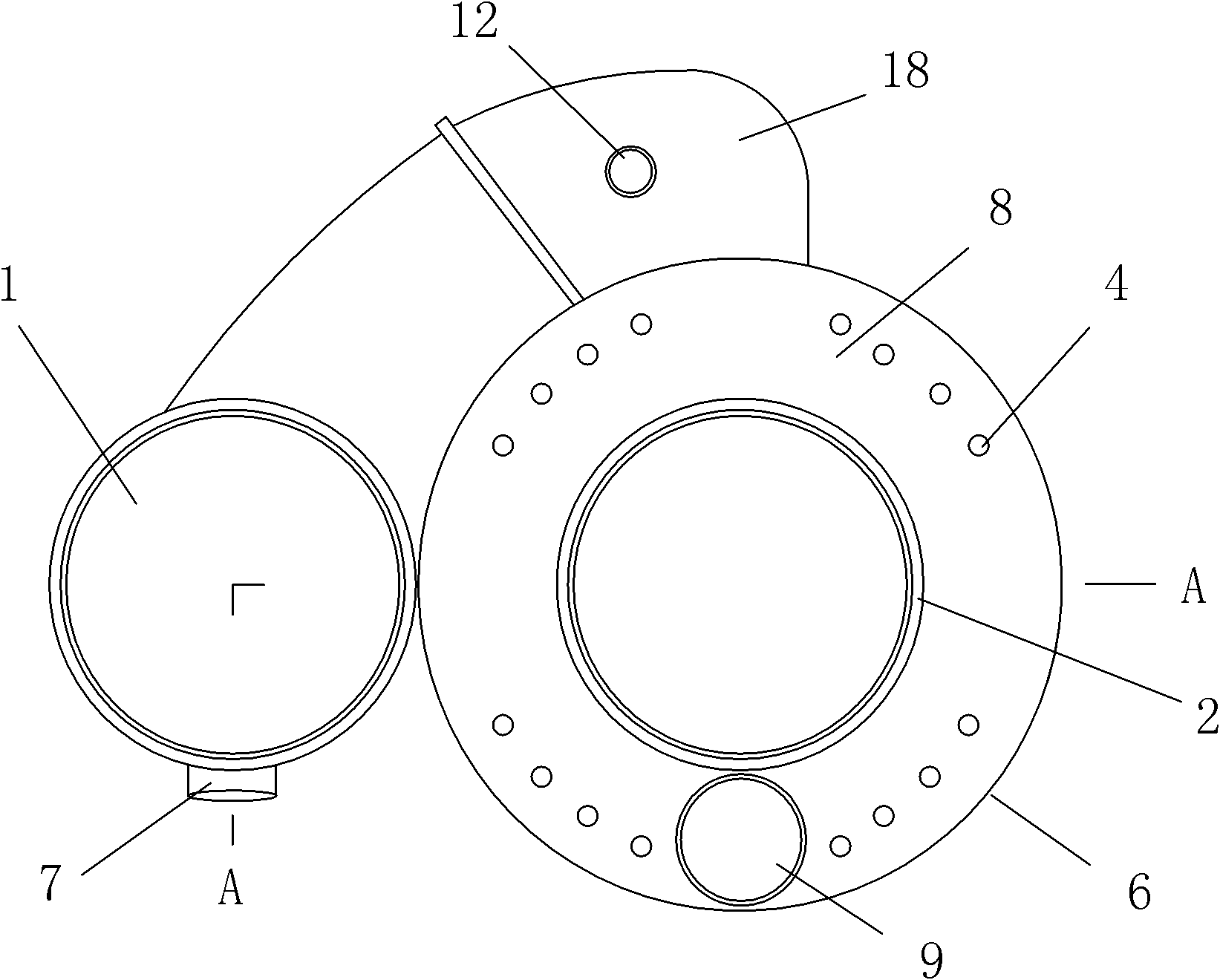
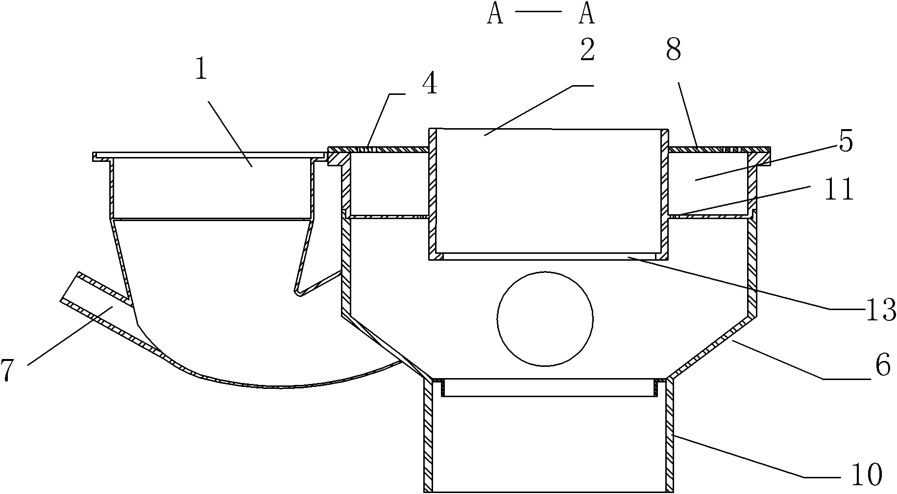
[0036] see figure 1 with Figure 4 , the water leaker 6 is formed by docking the upper interface 2 of the main riser and the lower interface 10 of the main riser, the outer side of the upper interface 2 of the main riser is provided with a sump 5, the interior is provided with an upper positioning ring 13, and the sump 5 is provided with a flow direction to the main vertical The water hole 11 of the lower interface 10 of the pipe, the lower interface 10 of the main riser is provided with a lower positioning ring 14, and the water trap 1 is connected to the lower interface 10 of the main riser through a siphon elbow 18 in a plug-in manner and assembled into one body. Water bend 1 is a pipe-like water-sealed water trap, the water-sealed water inlet end has a large diameter and volume, and the water-sealed water outlet end has a small diameter an...


PUM


Abstract

The invention discloses a combined drainage device, which comprises a water leakage device (6), wherein the water leakage device (6) is provided with main building siamese and a water collection tank (5); and a drain trap (1) is connected to the water leakage device (6) and is communicated with the main building siamese to form a whole. The combined drainage device is a drainage system, which can integrate the drain traps of a plurality of sanitary fixtures and floor drains in kitchens and toilets into a main water seal device and randomly realize serial connection and parallel connection, and is convenient to arrange and scientific, rational and humanized; positions of the sanitary fixtures, the floor drains and bath facilities in decoration can be randomly determined by users, and are not limited by the positions of the siameses; and the combined drainage device has the characteristics of simple structure, convenient and fast mounting, capability of saving the construction cost of developers, benefits to the state and citizens, low manufacture cost, vast market prospect, and high economic value and application value.

Description

technical field [0001] The invention relates to the technical field of kitchens, toilets, public bathing and sanitation places, and municipal drainage, in particular to a combined drainage device for drainage pipes widely used in the technical field of drainage pipes in the construction industry. Background technique [0002] my country's commercial housing construction is accelerating. In the current construction industry, according to the national construction design specifications, kitchen and bathroom drainage pipes are the corresponding interfaces of each sanitary ware. An independent water trap, water sealing device, and toilet seat must be installed. Squatting toilets must be equipped with water traps and water sealing devices, but the water in the water sealing device is too close to the human body and the ground, so it is easy to volatilize and become dirty after deterioration. The dirty water in the water sealing device often splashes on the buttocks when users use i...

Claims


Application Information

Patent Timeline
Patent Type & Authority Applications(China)
IPC IPC(8): E03C1/12E03C1/284
Inventor 张超
Owner 张超
Why Eureka
Try Eureka