Cyclone compressor
A scroll compressor and scroll technology, which is applied in the field of scroll compressors, can solve the problems of compressor performance degradation and inability to fully suppress pressure fluctuations in the compression chamber, and achieve high total adiabatic efficiency
- Summary
- Abstract
- Description
- Claims
- Application Information
AI Technical Summary
Problems solved by technology
Method used
Image
Examples
no. 1 approach
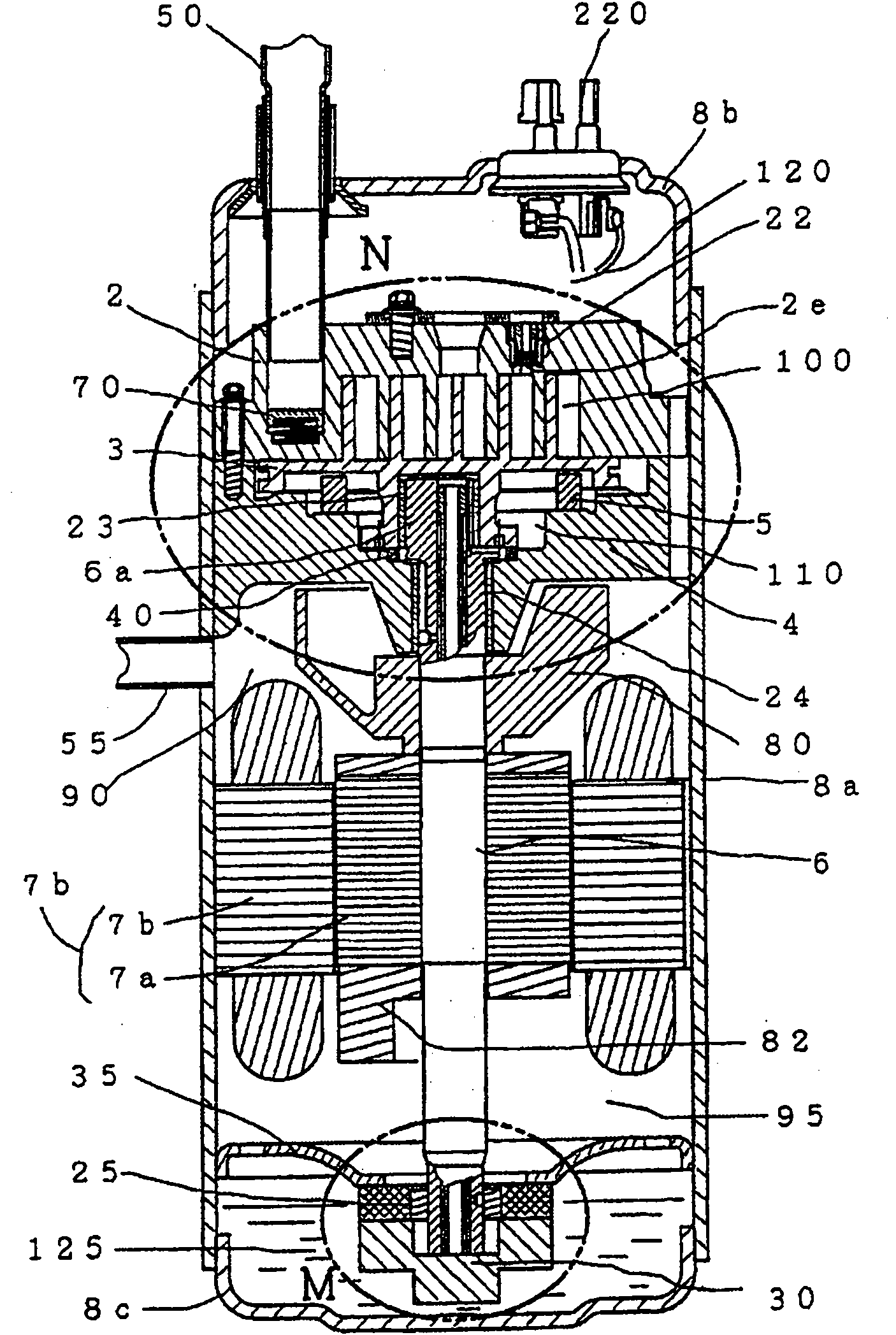
[0074] according to Figure 1-7 , Figure 23 and Figure 24 A first embodiment in which the present invention is applied to an orbiting urging scroll compressor in which the non-orbiting scroll member is fixed to the housing is described. The scroll member is provided with a back pressure chamber on the back side of the orbiting end plate (anti-compression chamber side) of the end plate of the orbiting scroll member. The rotating member exerts force. Here, the scroll member that has been called "non-orbiting" is called "fixed" for explanation (for example, the non-orbiting end plate is called a fixed end plate, and the non-orbiting scroll is called a fixed scroll. Wait).
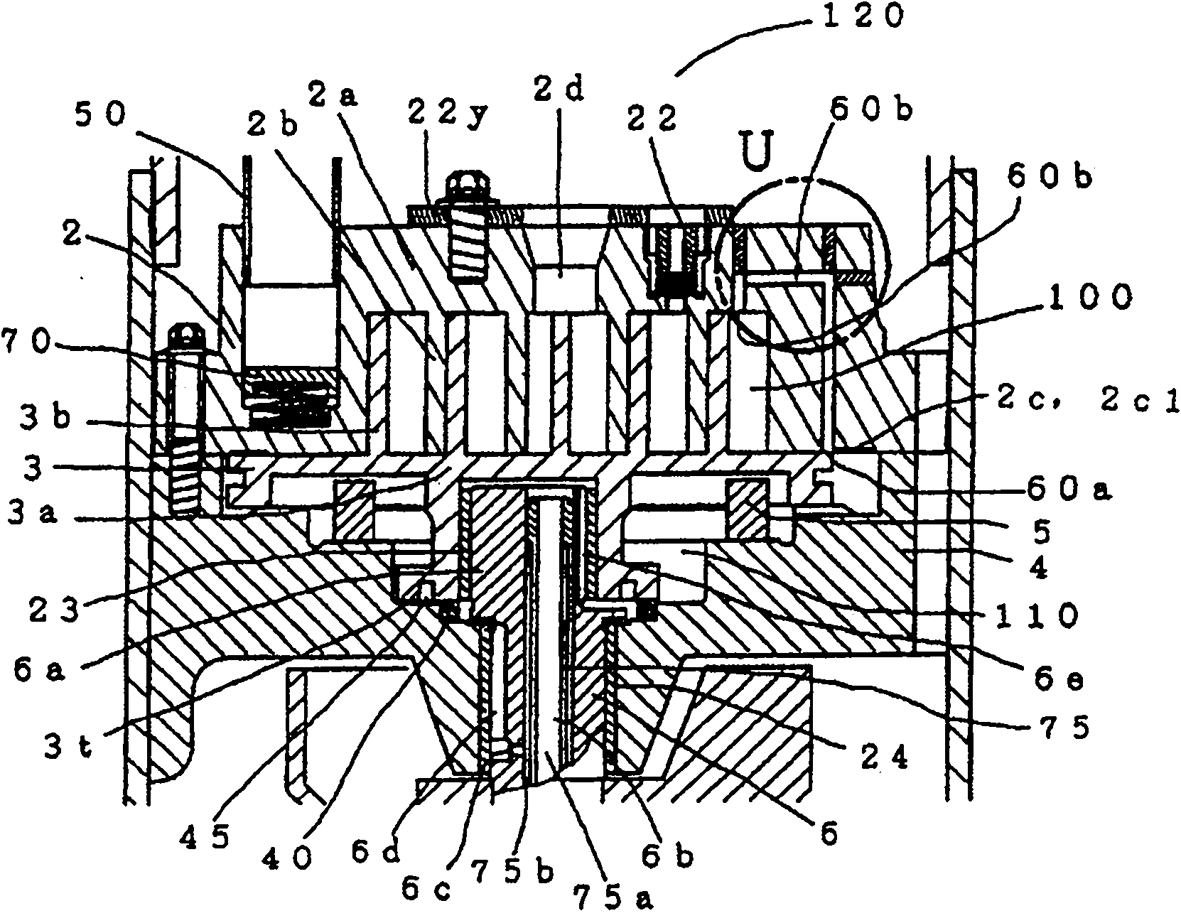
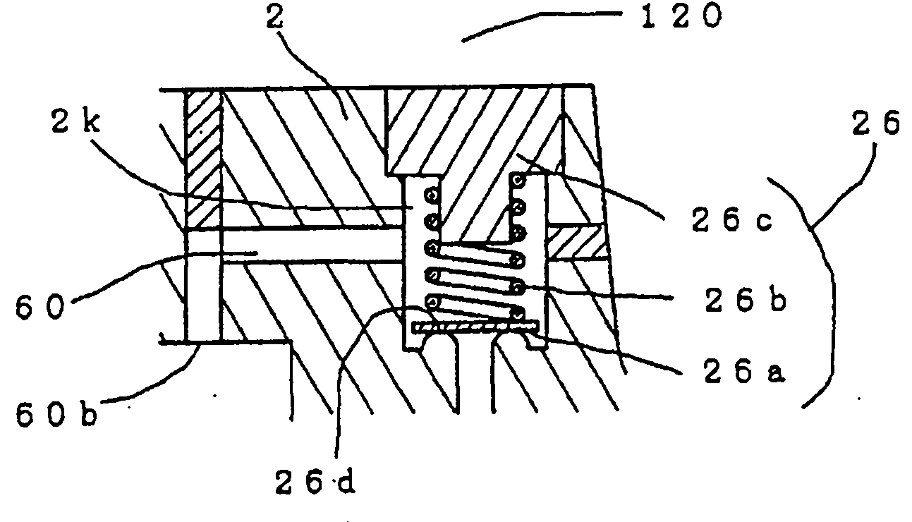
[0075] figure 1 It is a longitudinal sectional view of a scroll compressor. Figure 2(A) is an enlarged view of the compression mechanism ( figure 1 N part of the valve), Fig. 2(B) is an enlarged view of the differential pressure control valve in the case of the valve type (U part of Fig. 2(A)), image ...
no. 2 approach
[0104] Next, use an enlarged view of the vicinity of the opening on the compression chamber side ( Figure 4 Part P2) of Figure 8A scroll compressor according to a second embodiment of the present invention will be described. In the second embodiment, parts different from those in the first embodiment will be described, and the same parts will be omitted. In the second embodiment, the compression-chamber-side opening 60b is provided at a position about 240 degrees inward from the inner-line-side winding end point of the fixed scroll 2b. Compared with the above-mentioned first embodiment, the angle away from the inner thread side winding end point is smaller, so the compression chamber side opening 60b starts communicating with the suction chamber 105 before the start of compression. However, in this case, there is no essential difference except that the center of the back pressure fluctuation is close to the suction pressure, and the same effect as that of the first embodim...
no. 3 approach
[0106] Next, use an enlarged view of the vicinity of the opening on the compression chamber side ( Figure 4 Part P1) of Figure 9 A scroll compressor according to a third embodiment of the present invention will be described. In the third embodiment, parts different from those in the first embodiment will be described, and the same parts will be omitted. This third embodiment is an embodiment in which the compression chamber side opening 60b is set on the radially outer side with respect to the center of the fixed dedendum. However, a part of the compression chamber side opening is formed at a position away from the side surface of the fixed scroll 2b by more than the addendum width of the orbiting scroll 3b, and a section communicating with the fixed outer line side compression chamber 100b is ensured. The communication angle section with the fixed inner line side compression chamber 100a is larger than the communication angle section with the fixed outer line side compres...
PUM
 Abstract
Description
Claims
Application Information
 - R&D
- Intellectual Property
- Life Sciences
- Materials
- Tech Scout
- Unparalleled Data Quality
- Higher Quality Content
- 60% Fewer Hallucinations
Browse by: Latest US Patents, China's latest patents, Technical Efficacy Thesaurus, Application Domain, Technology Topic, Popular Technical Reports.
© 2025 PatSnap. All rights reserved.Legal|Privacy policy|Modern Slavery Act Transparency Statement|Sitemap|About US| Contact US: help@patsnap.com


