Lens barrel

A technology of lens barrel and rotating frame, applied in instruments, installation, optics, etc., can solve the problems of easy change in distance and creeping teeth between gears.

Inactive Publication Date: 2010-12-01
OLYMPUS CORP
View PDF7 Cites 6 Cited by
  • Summary
  • Abstract
  • Description
  • Claims
  • Application Information

AI Technical Summary

Problems solved by technology

[0007] Here, when the ends of the cam groove in the shortening direction are formed in an open state so that the cam follower engages in the cam groove, a gap is generated between the cam groove and the cam follower, and the frame is rotated. The distance between the gear and the gear meshing with it is prone t

Method used


Image

  • Lens barrel
  • Lens barrel
  • Lens barrel

Examples


Embodiment Construction

[0024] Hereinafter, preferred embodiments of the present invention will be described with reference to the drawings. In addition, in each drawing used in the following description, in order to make each constituent element a recognizable size on the drawing, the scale is different for each constituent element, and the present invention is not limited to those shown in these drawings. The number of constituent elements, the shape of the constituent elements, the size ratio of the constituent elements, and the relative positional relationship of each constituent element are described.

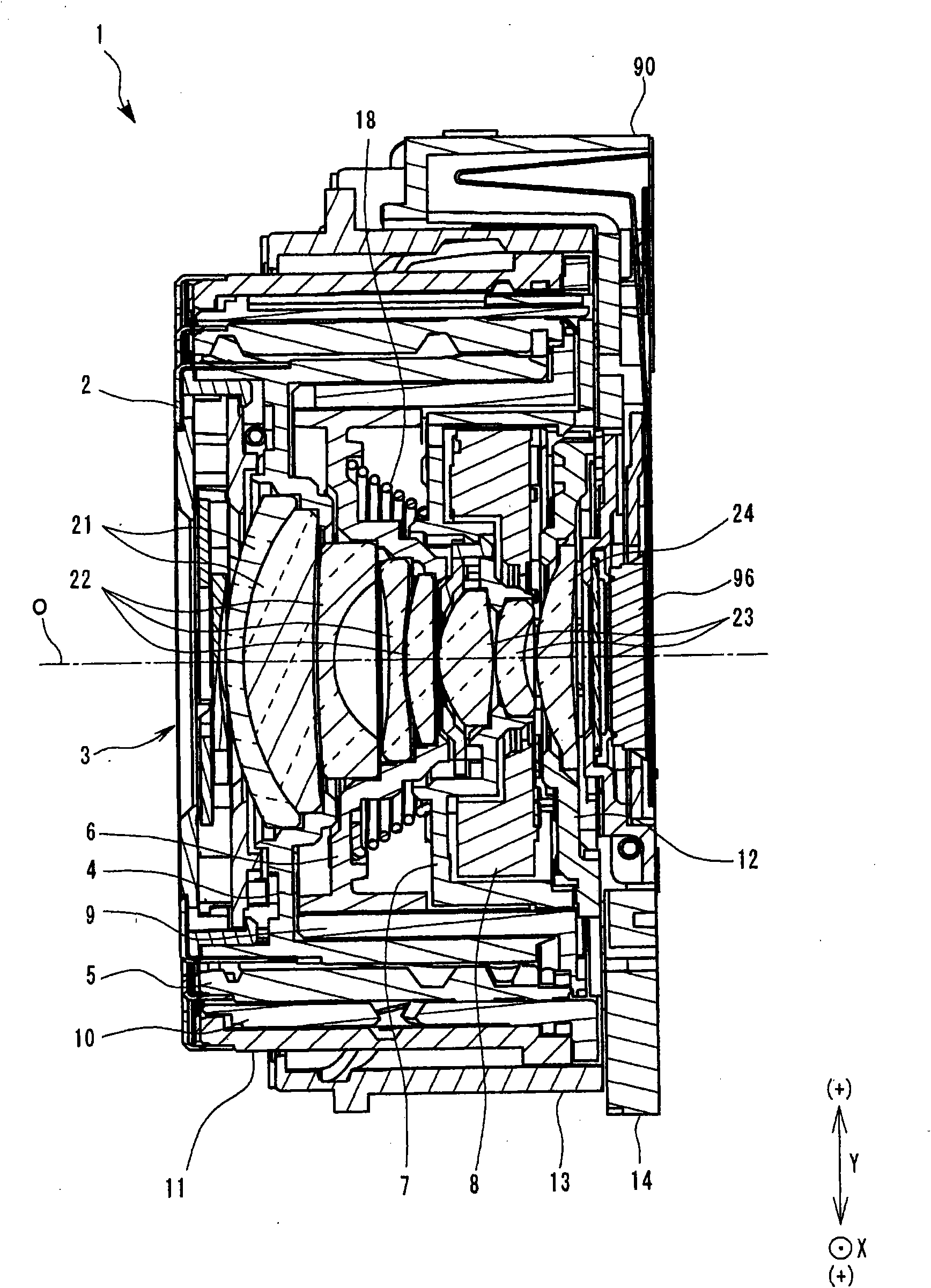
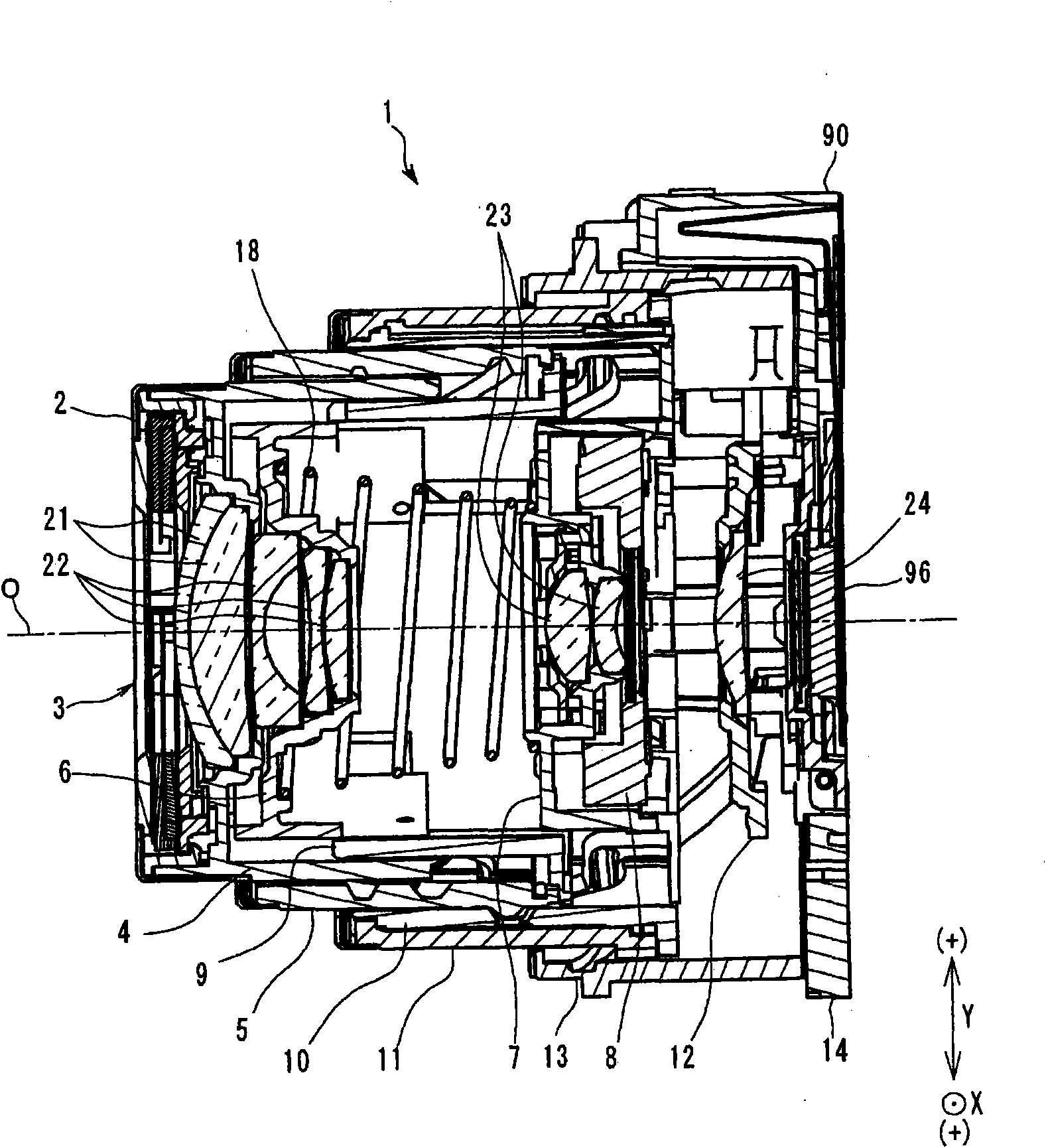
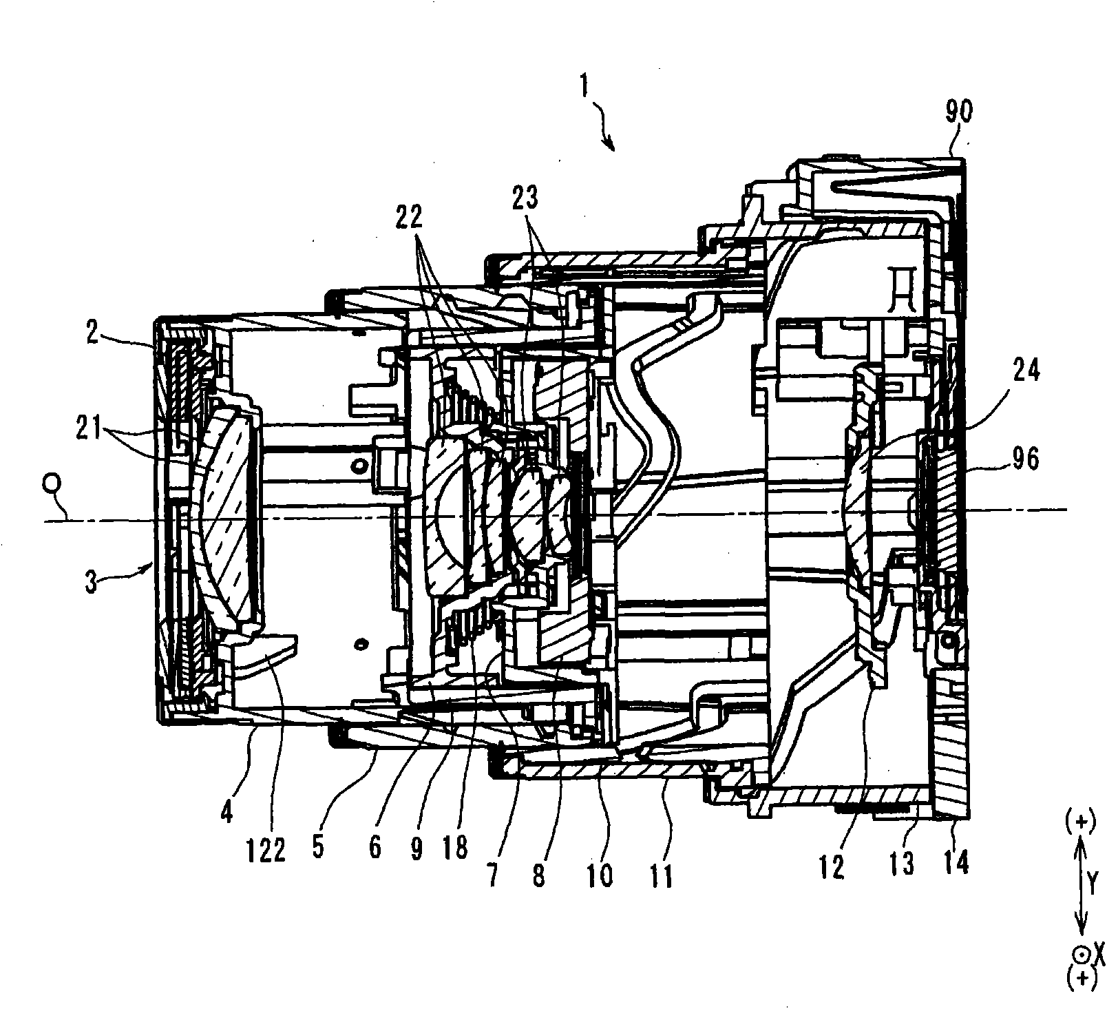
[0025] Such as Figure 1 to Figure 3 As shown, the lens barrel 1 of the present embodiment is a device for holding a photographic optical system consisting of a first group lens 21 having a positive refractive power, a second group lens 22 having a negative refractive power, and a lens group having a negative refractive power. The four-group structure composed of the third group lens 23 with pos...


PUM


Abstract

The present invention provides a lens barrel, including a fixed frame having a cam groove, one end part of which arranged on a first direction side is an open end; a rotary frame having a plurality of cam followers on its peripheral surface; a first gear wheel arranged on the peripheral surface of the rotary frame; a second gear wheel joggled with the first gear wheel; and an electric motor for driving the second gear wheel to rotate, and making the rotary frame to move toward the first direction by rotating the rotary frame toward a second rotating direction. The lens barrel is characterized in that the lens barrel is provided with a convex part on the open end, and the convex part prevents the cam followers from moving toward the radial outer side when the rotation of the rotary frame toward the second rotating direction is limited by a butting part.

Description

technical field [0001] The present invention relates to a lens barrel that moves a frame member forward and backward by using a cam groove and an electric motor. Background technique [0002] In a lens barrel used in a photographing device such as a camera, a plurality of cylindrical frame members for holding a lens etc. are arranged concentrically, and the sinking is carried out by moving the plurality of frame members relatively forward and backward along the optical axis direction. body movement or zoom movement. [0003] As a structure for relatively moving the frame member forward and backward in the direction of the optical axis, the following structure is generally adopted: a fixed frame with a cam groove provided on the inner periphery; The rotating frame of the cam follower engaged with the groove moves forward and backward in the direction of the optical axis according to the contour of the cam groove by rotating the rotating frame around the optical axis relative...

Claims


Application Information

Patent Timeline
IPC IPC(8): G02B7/04
Inventor 石塚和宜青木翔平
Owner OLYMPUS CORP
Why Eureka
Try Eureka