Electronic component cutting and stripping machine and method thereof

A technology of electronic components and stripping machines, applied in the direction of electrical components, circuits, semiconductor devices, etc., can solve the problems of increasing work time, reducing production efficiency, and consuming work time, so as to reduce the process and work time and improve production efficiency , cost-saving effect

Inactive Publication Date: 2010-12-01
PROV TECH CORP
View PDF0 Cites 16 Cited by
  • Summary
  • Abstract
  • Description
  • Claims
  • Application Information

AI Technical Summary

Problems solved by technology

[0003] In this cutting / forming process, in order to prevent the LED from moving during the cutting operation, a ring-shaped frame must be pasted on the tape first, and the tape edge outside the ring-shaped frame must be cut off before the lead frame with LED can be pasted on the tape In addition, it not only consumes cost, but also increases the procedures such as pasting the ring frame and cutting the tape edge material, which consumes operating time
[0004] The cutting / forming process manually sticks the lead frames with LEDs on the tape inside the ring frame one by one, and then transfers each ring frame to the cutting machine for cutting. When the number of lead frames is large, the manual sticking operation It is quite time-consuming and labor-intensive, resulting in the loss of production efficiency
[0005] The cutting / forming process must use a special material of U-V tape and irradiate the tape with a UV lamp to remove the adhesiveness of the tape. Not only the cost of the tape is high, but also UV lamp equipment needs to be purchased, resulting in increased costs and time-consuming work.
[0006] As the volume of LEDs is becoming smaller and smaller, it is quite difficult for the picker and placer of the material transfer device to take out the tiny LEDs on the tape, resulting in the loss of materials that are not easy to receive

Method used


Image

  • Electronic component cutting and stripping machine and method thereof
  • Electronic component cutting and stripping machine and method thereof
  • Electronic component cutting and stripping machine and method thereof

Examples


Embodiment Construction

[0039] In order to enable your examiner to have a further understanding of the present invention, a preferred embodiment and accompanying drawings are described in detail as follows:

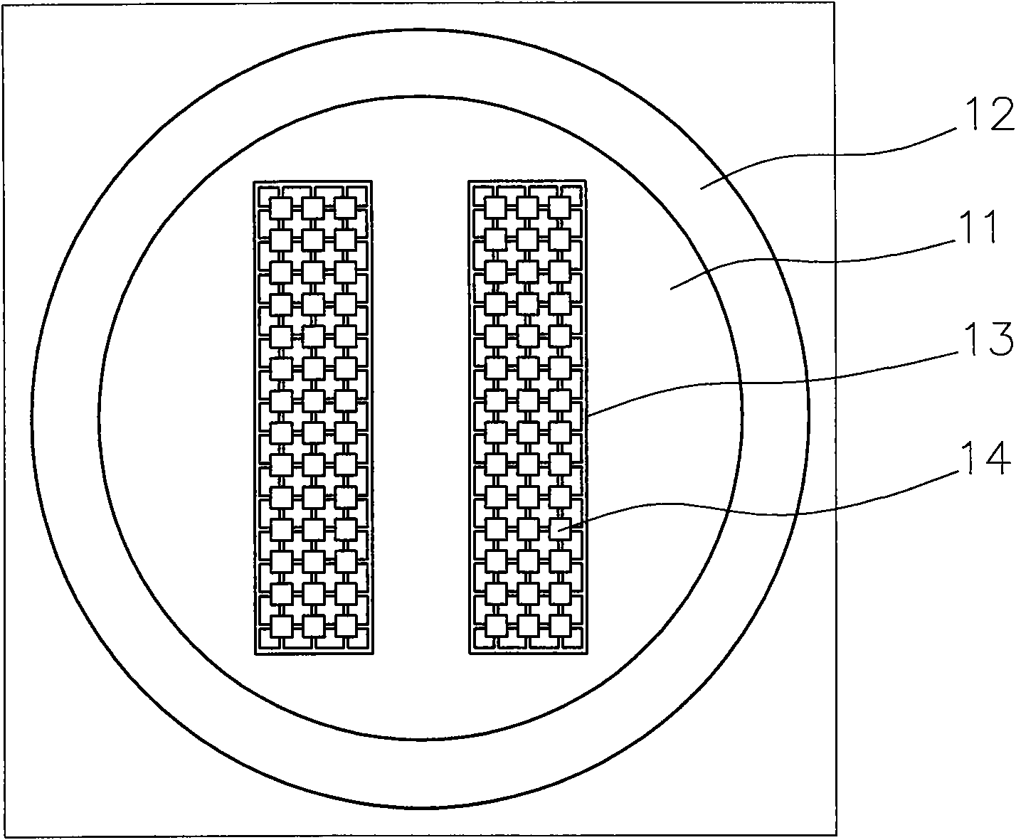
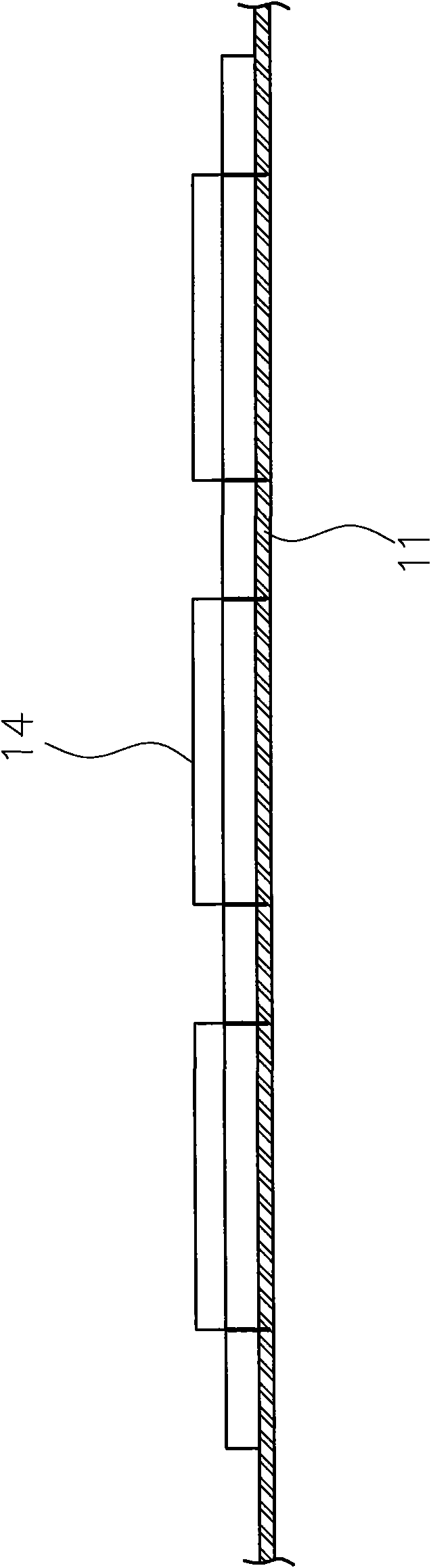
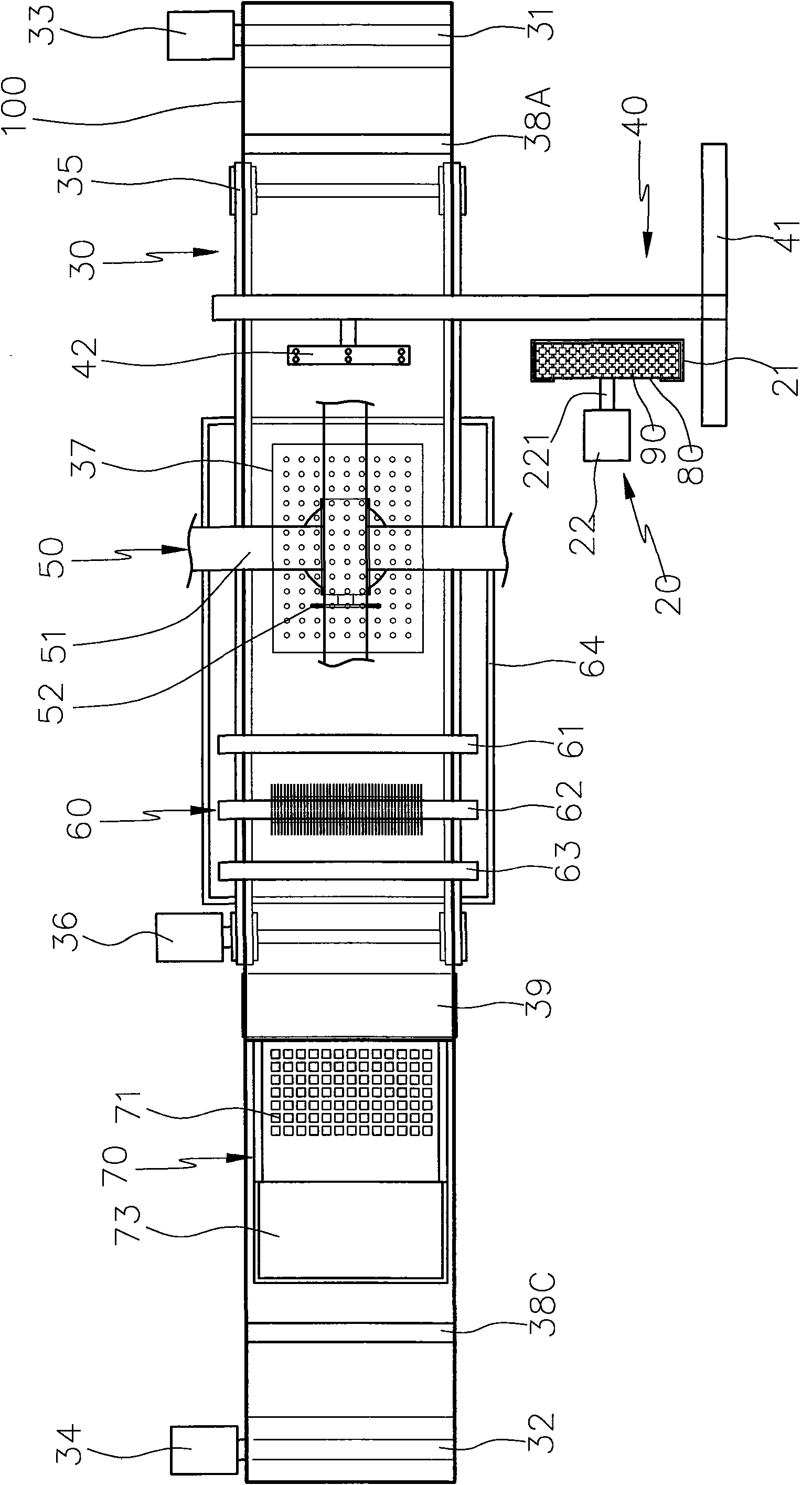
[0040] see image 3 , Figure 4, the cutting and stripping machine of the present invention includes a feeding device 20, a conveying device 30, a material shifting device 40, a cutting device 50, a cleaning device 60 and a receiving device 70, wherein the feeding device 20 is provided with a magazine 21 for use To accommodate a plurality of lead frames 80 with LEDs 90; and the feeding device 20 is provided with a pushing mechanism 22 with a pushing member 221 for pushing out the lead frames 80 for feeding. The pushing mechanism 22 can be driven by a driving source to drive the pushing member 221 to move up and down or to move laterally. To convey the adhesive tape 100 , the conveying mechanism is provided with a first shaft 31 at the front, and the conveying mechanism is provided with a secon...


PUM


Abstract

The invention provides an electronic component cutting and stripping machine and a method thereof. The electronic component cutting and stripping machine comprises a feeding device, a conveying device, a shifting device, a cutting device, a cleaning device and a receiving device; wherein the feeding device contains a plurality of lead frames provided with electronic components; the conveying device is provided with a conveying mechanism and a stripping platform provided with a bevel, and the conveying mechanism is used for conveying adhesive belts; the shifting device utilizes a picking and placing device to take out the lead frames provided with electronic components from the feeding device, the lead frames are shifted and adhered onto the adhesion belts on the conveying device, and then the adhesion belts and the lead frames are conveyed to the position below the cutting device; the cutting device utilizes a cutter to cut the lead frames on the adhesive belts, so as to obtain a plurality of independent electronic components, and the conveying mechanism conveys the independent electronic components and adhesive belts to the position below the cleaning device; and the cleaning device utilizes a cleaner to clean dust on the electronic components, then the conveying mechanism causes the adhesive belts to bend down along the bevel of the stripping platform, so as to strip the electronic components, and the electronic components are dropped into the receiving device to be received and contained.

Description

technical field [0001] The invention relates to an electronic component cutting and stripping machine and a method thereof, in particular to an electronic component cutting and stripping machine and a method thereof that can reduce the manufacturing process and working time, and can easily strip electronic components, thereby improving production efficiency and saving costs. Background technique [0002] Nowadays, in the back-end process of LED electronic components, multiple well-tested dies are sucked onto the lead frame for die bonding, and then wire bonded and molded. And cutting / forming (Trim / Form), final testing (test) and packaging, that is to complete the back-end process of LEDs. Among them, the cutting / forming process is to separate the LEDs assembled on the lead frame independently, in order to prevent the LED from cutting To move freely during the operation, the method is to glue a hollow ring frame 12 on the tape 11 first, and cut off the tape edges outside the ...

Claims


Application Information

Patent Timeline
Patent Type & Authority Applications(China)
IPC IPC(8): H01L21/00H01L21/78H01L33/00B28D5/00
Inventor 邱文国
Owner PROV TECH CORP
Why Eureka
Try Eureka