
Resource allocation method, device and system

A resource allocation and resource technology, applied in the field of communication, can solve problems such as unpredictable interference and increased interference, and achieve the effect of improving system performance and expanding the range of resource selection

Inactive Publication Date: 2010-12-01
HUAWEI TECH CO LTD +1
View PDF0 Cites 5 Cited by
  • Summary
  • Abstract
  • Description
  • Claims
  • Application Information

AI Technical Summary

Problems solved by technology

[0004] In the process of implementing the present invention, the inventors found that there are at least the following problems in the above-mentioned prior art: the sharing of subcarriers makes the interference unpredictable. Interference from other cells increases

Method used


Image

  • Resource allocation method, device and system
  • Resource allocation method, device and system
  • Resource allocation method, device and system

Examples


Embodiment Construction

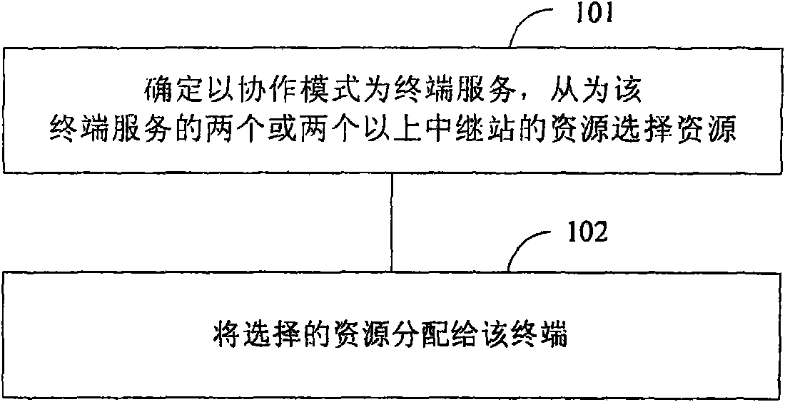
[0026] The resource allocation method in the embodiment of the present invention includes:

[0027] When the terminal is served in the cooperative mode, resources are selected from the resources of two or more relay stations serving the terminal; and the selected resources are allocated to the terminal.

[0028] The above-mentioned resources of each RS may include subcarrier groups or frequency bands.

[0029] Terminals in the relay system can be divided into two categories: terminals using cooperative mode services and terminals using non-cooperative mode services. Serving the terminal in the cooperative mode refers to serving the terminal through two or more RSs in the relay system. Whether the terminal adopts the cooperative mode for service can be determined according to the preset result, or can be determined according to the specific attributes of the terminal. It can be determined by using attributes such as the location of the terminal, received power, and received SI...


PUM


Abstract

The invention discloses a resource allocation method, a resource allocation device and a resource allocation system, which are used for optimizing resource allocation and reducing interference among cells. The method comprises the following steps of: when a service is provided for a terminal in a cooperative mode, selecting resources from the resources of two or more relay stations serving the terminal; and allocating the selected resources to the terminal. Through the technical scheme provided by the invention, the resource selection range of the terminal adopting the cooperative mode is expanded, more rational resources can be allocated to the terminal adopting the cooperative mode, system performance is improved and the problem of too much interference to the other cells is solved.

Description

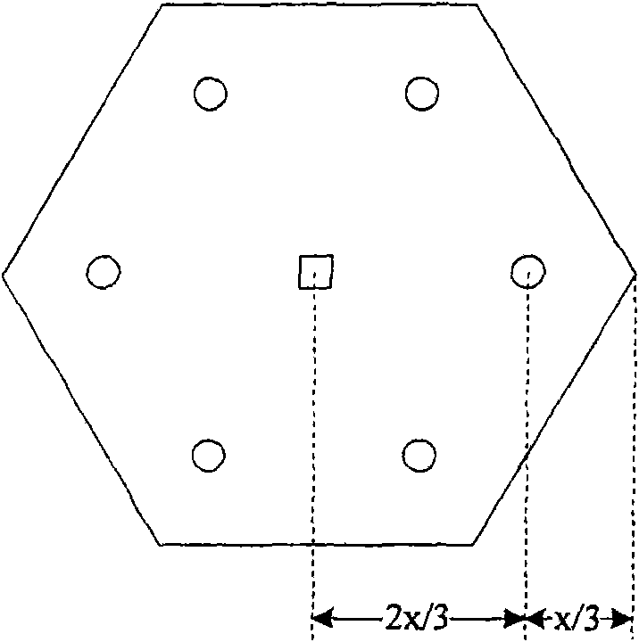
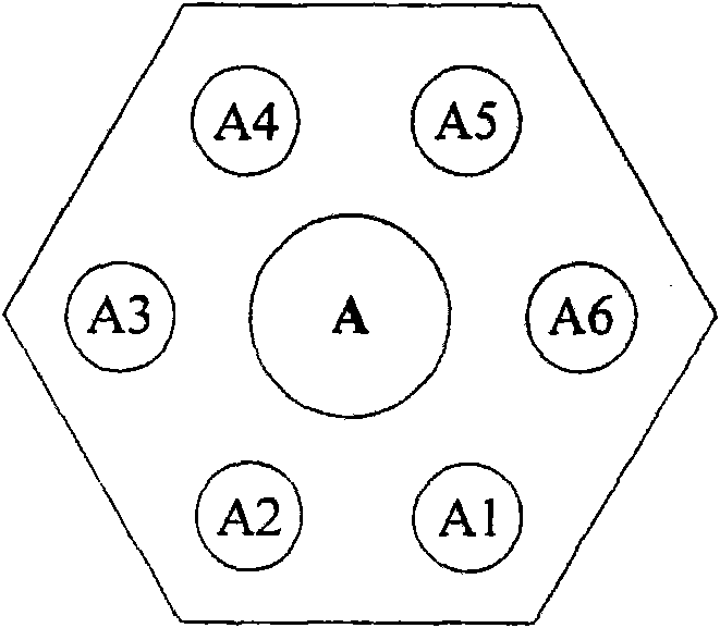
technical field [0001] The present invention relates to the field of communication technologies, and in particular to a resource allocation method, device and system. Background technique [0002] The future communication system should meet the user's demand for high data rate services as much as possible within the coverage of the entire network, but the existing cellular network architecture obviously cannot meet the requirements, and introducing relay technology into the cellular network has become an effective and feasible method. figure 1 A typical fixed relay cellular structure is given. Six RSs (Relay Stations, relay stations) (shown by dots) are placed in the cell. On the connection line, the distance from the base station is 2 / 3 of the cell radius, which is evenly covered in the entire cellular network. [0003] There is a subcarrier allocation scheme in the prior art, considering the clustering of single cells, the specific scheme is as follows: the cellular struc...

Claims


Application Information

Patent Timeline
IPC IPC(8): H04W16/06H04W16/26H04W72/04H04B7/26
Inventor 王晓湘吴聪婷张鸿涛王玉龙
Owner HUAWEI TECH CO LTD
Learn More