Improvements in or relating to shredder cutters

A technology of shredders and knives, applied in the direction of cutting tools, agricultural machinery and implements, cutting equipment, etc., can solve problems such as complexity, fiber damage, and poor efficiency

Inactive Publication Date: 2010-12-01
ROBERT BOSCH GMBH
View PDF1 Cites 9 Cited by
  • Summary
  • Abstract
  • Description
  • Claims
  • Application Information

AI Technical Summary

Problems solved by technology

[0003] The disadvantage of this arrangement is that, while favoring the destruction of fibers, crushing is a relatively inefficient use of its available power compared to cutting
The arrangement works but is complicated to manufacture and in good working order to ensure the blades stay in the correct orientation

Method used


Image

  • Improvements in or relating to shredder cutters
  • Improvements in or relating to shredder cutters
  • Improvements in or relating to shredder cutters

Examples


Embodiment Construction

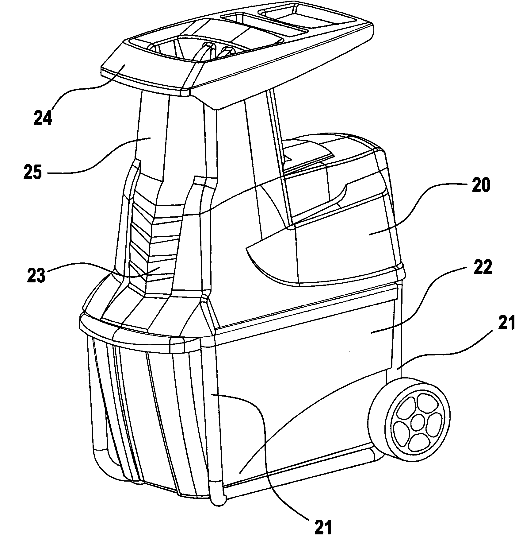
[0032] figure 2 Shown is a shredder body 20 comprising a shredder knife assembly mounted on a frame 21 above a collection box 22 in operative communication with an outlet 23 of the shredder body 20 . The shredder body 20 has an inlet or funnel 24 for receiving vegetation to be chopped, such as branches or treetops. Feed port 24 is separated from the knife assembly by feed slot 25 to prevent user access to the knife assembly during use.

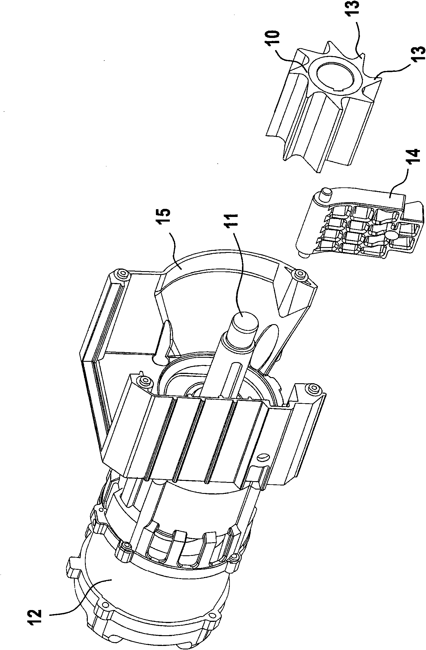
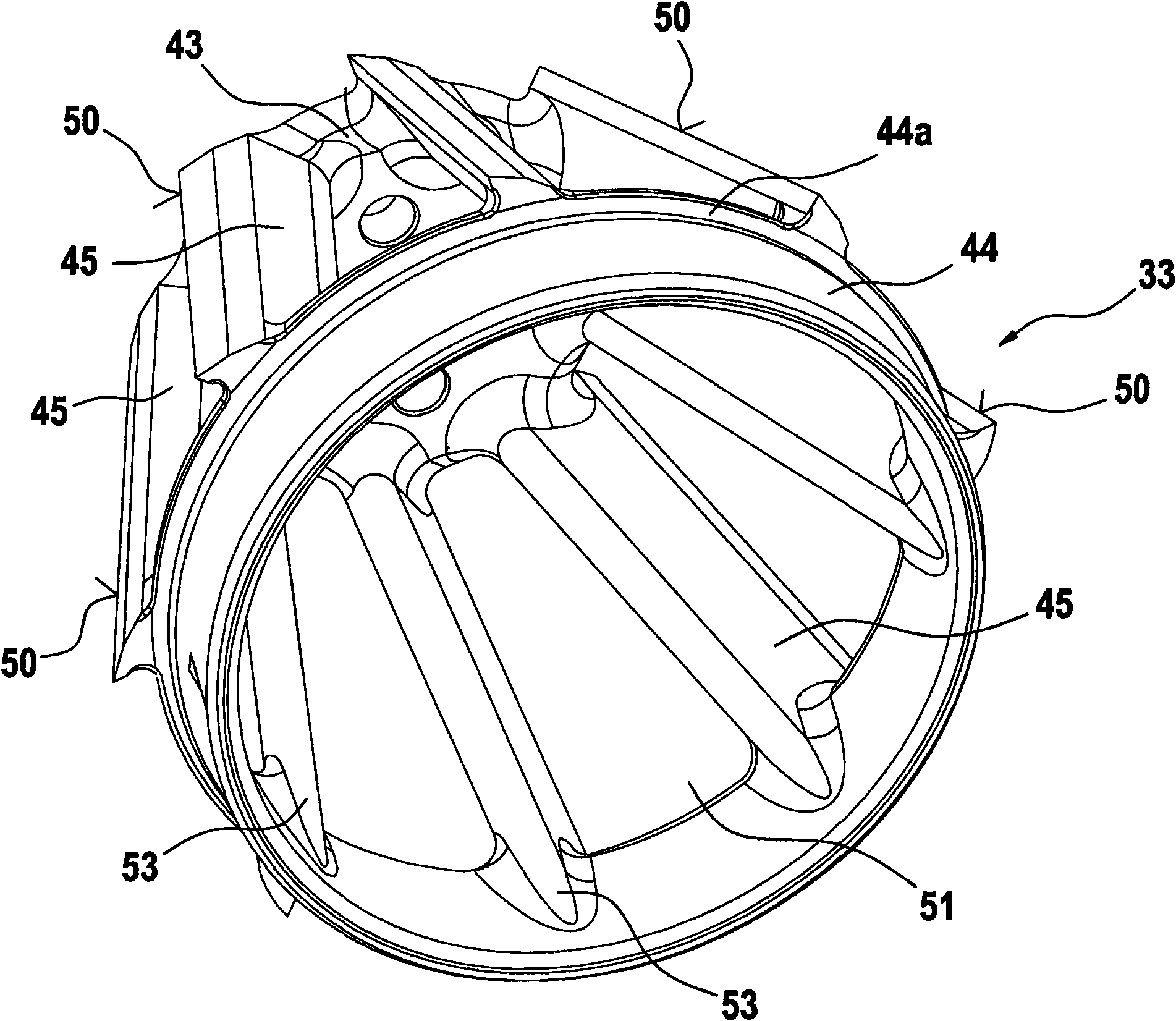
[0033] refer to Figure 5 , shows a cutter assembly of a shredder comprising a motor and gearbox unit 30 with a rotating shaft 31 carrying a torque transfer device 32 for transferring torque to the cutter. The cutting element 33 according to the invention is mounted on the conveyor device 32 . The knife assembly includes a housing 34 to house a cutting element 33 and define a shredding cavity. The housing includes an operative upper opening or inlet 35 for receiving vegetation to be chopped and an operative lower opening or outlet 36 for...


PUM


Abstract

The present invention relates to improvements in or relating to cutters for shredders, in particular to cutters for shredders, in particular for vegetation shredders, suitably of the type used for shredding tree branches and garden waste. The present invention relates to a cutter (33) and method for manufacturing the cutter by means of investment casting. We describe a cutting element (33) for a vegetation shredder, the cutting element being a hollow unitary element comprising a plurality of elongate blades (45) arranged in a generally cylindrical configuration between a proximal and distal support elements (43, 44). The cylindrical configuration has a generally frusto-conical form, the distal support element (44) forming a base of said frusto-conical form. The cutting element is formed with elongate apertures (51) between adjacent blades (45).

Description

technical field [0001] The present invention relates to improvements in or relating to knives for shredders, particularly vegetation shredders, of the type suitable for shredding twigs and garden waste. The present invention relates to a novel knife and a method for manufacturing the same, and to a shredder comprising the same. Background technique [0002] figure 1 A typical prior art shredder assembly for a vegetation shredder is shown. The assembly comprises a cylindrical chopping element 10 carried by a shaft 11 of a reduction gearbox connected to a motor 12 to cause rotation. The element 10 comprises teeth 13 which, in use, bear against a reaction plate 14 . The assembly is surrounded by an enclosure 15 intended to contain any vegetation impinging on the assembly and direct it between the shredder elements 10 and the reaction plate 14 to be crushed and cut. In a typical shredder, the shredder element 10 has eight blades and rotates at about 40 revolutions per minute...

Claims


Application Information

Patent Timeline
IPC IPC(8): B02C18/18A01F29/06A01G3/00B02C18/14
CPCA01G3/002B02C18/186B02C18/144B02C2201/066B02C2018/188
Inventor R·比德曼P·辛普森T·科奇什A·福尔斯P·海伍德B·斯梅尔
Owner ROBERT BOSCH GMBH
Why Eureka
Try Eureka