Antenna device and wireless communication device using the same

一种天线装置、无线通信的技术,应用在表面安装型天线的导体图案形状,无线通信机领域,能够解决不能有效利用基体、天线装置大型化、天线特性变化等问题,达到增强电磁耦合、确保长度和面积、高效利用的效果

Inactive Publication Date: 2010-12-01
TDK CORPARATION
View PDF3 Cites 13 Cited by
  • Summary
  • Abstract
  • Description
  • Claims
  • Application Information

AI Technical Summary

Problems solved by technology

However, since the feed conductor is formed on both the upper surface and the side surface of the base, it is necessary to ensure a wide area for forming the feed conductor, so there is a problem that the main surface of the base cannot be effectively used due to the radiation conductor, resulting in an increase in the size of the entire antenna device.
[0010] also, Figure 18 , Figure 19 The described antenna device has the problem that the antenna characteristics vary greatly depending on the mounting position on the printed circuit board.
This problem is mentioned in Patent Document 3, where the antenna characteristics change due to changes in the positional relationship between the ground pattern on the printed circuit board and the antenna device

Method used


Image

  • Antenna device and wireless communication device using the same
  • Antenna device and wireless communication device using the same
  • Antenna device and wireless communication device using the same

Examples


Embodiment Construction

[0048] Hereinafter, preferred embodiments of the present invention will be described in detail with reference to the accompanying drawings.

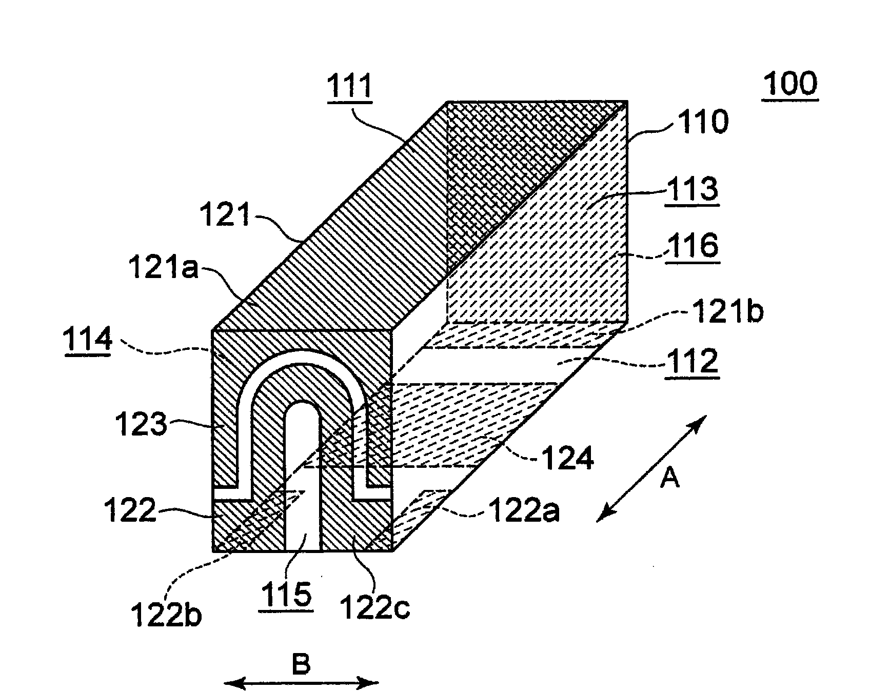
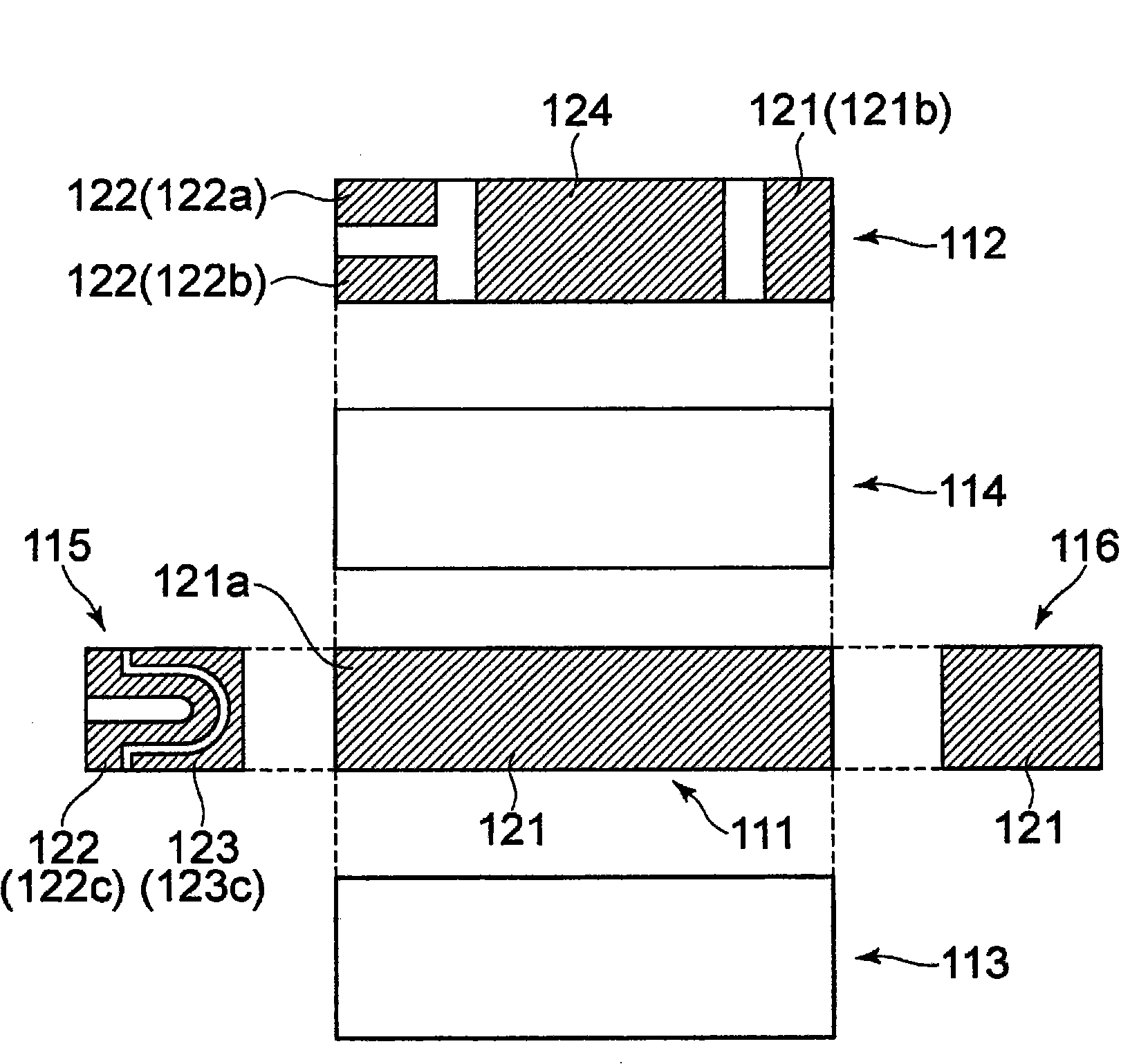
[0049] figure 1 It is a schematic perspective view showing the configuration of the antenna device 100 according to the preferred first embodiment of the present invention. also, figure 2 is a developed view of the antenna device 100 .

[0050] Such as figure 1 and figure 2 As shown, the antenna device 100 of the present embodiment is constituted by a base 110 made of a dielectric and a plurality of conductor patterns formed on the base 110 . The base body 110 has a rectangular parallelepiped shape with the A direction as its length direction. Thus, the base body 110 has four surfaces 111 to 114 parallel to the A direction, and two surfaces 115 and 116 perpendicular to the A direction. Among them, the surface 112 is a mounting surface for a printed circuit board.

[0051] The material of the substrate 110 is not particularly l...


PUM


Abstract

To obtain, in an antenna device of such a type that the device supplies radiation current by electromagnetic field coupling, a high radiation efficiency by increasing the electromagnetic field coupling. An antenna device comprises a conductor pattern including a base substance (110), a radiation conductor (121) formed on the base substance (110), a feed conductor (122), and a coupling conductor (123). The feed conductor (122) and the coupling conductor (123) are both formed on a side surface (115) of the base substance (110). One end (122a) of the feed conductor (122) is connected to a feed line, and the other end (122b) is connected to a ground pattern. The coupling portion (122b) of the feed conductor (122) is generally U-shaped and is electromagnetically coupled to the coupling conductor (123). The feed conductor (122) is gently curved, so that the electric field concentration hardly occurs. In addition, it is possible to lengthen the distance of the feed conductor (122), so that astronger electromagnetic coupling with the coupling conductor (123) can be obtained.

Description

technical field [0001] The present invention relates to an antenna device, and more particularly, to a conductor pattern shape of a surface-mounted antenna used in a mobile phone or the like. Furthermore, the present invention relates to a wireless communication device using the antenna device. Background technique [0002] A small antenna device is built into a small wireless communication device such as a mobile phone. Figure 18 and Figure 19 It is a schematic perspective view showing an example of the configuration of a conventional antenna device. [0003] Figure 18 The shown antenna device has a substrate 1 made of a rectangular parallelepiped dielectric, and a linear radiation conductor 2 disposed at the center of the upper surface of the substrate 1 in the width direction. One end of the radiation conductor 2 is connected to a feed electrode (feed line) via a gap g. )4 connection, and the other end is connected to the grounding conductor 3 provided on the bottom ...

Claims


Application Information

Patent Timeline
Patent Type & Authority Applications(China)
IPC IPC(8): H01Q1/38H01Q1/24H01Q9/30
CPCH01Q1/2283H01Q1/243H01Q9/42H01Q1/38
Inventor 张原康正
Owner TDK CORPARATION
Why Eureka
Try Eureka