Method for accurate auto-calibration of phased array antennas

A phased array antenna, antenna element technology, applied in antennas, radio wave measurement systems, instruments, etc., can solve problems such as time-consuming

Active Publication Date: 2010-12-01
THE BOEING CO
View PDF5 Cites 39 Cited by
  • Summary
  • Abstract
  • Description
  • Claims
  • Application Information

AI Technical Summary

Problems solved by technology

This process is time consuming and is typically only valid at the frequen

Method used


Image

  • Method for accurate auto-calibration of phased array antennas
  • Method for accurate auto-calibration of phased array antennas
  • Method for accurate auto-calibration of phased array antennas

Examples


Embodiment Construction

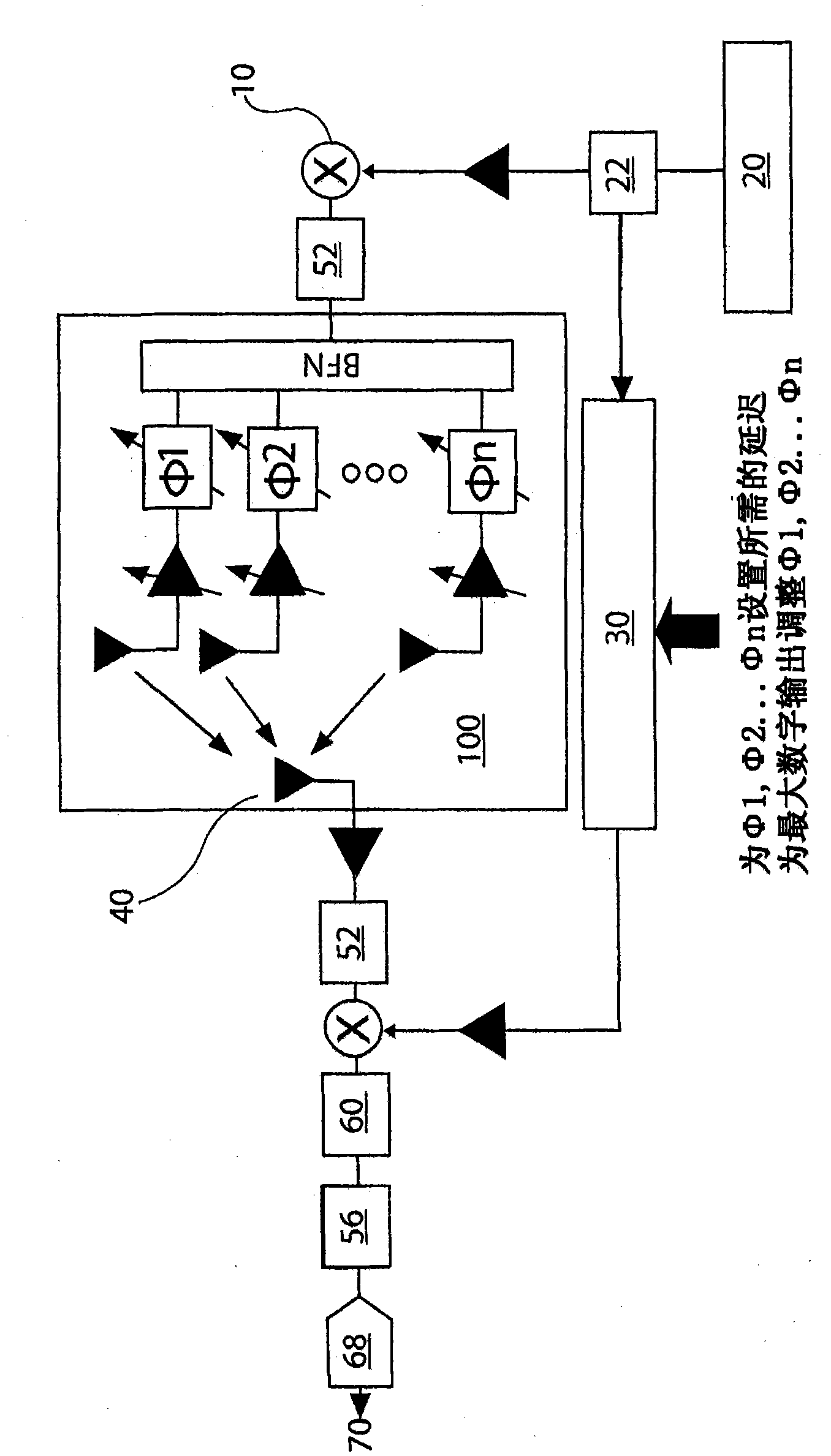
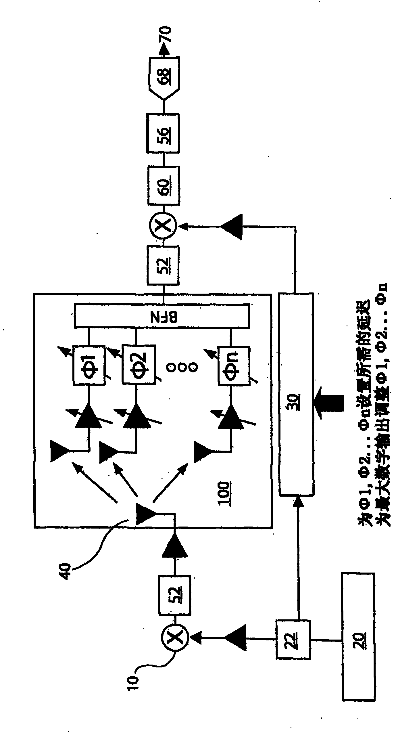
[0032] In the following description, reference is made to the accompanying drawings, which form a part hereof, and in which, for purposes of illustration, show various embodiments of the invention.

[0033] The present invention provides a phased array antenna having test probes in the form of RF radiators deployed within or adjacent to the array. The test probe RF radiator operates independently of the array, providing and receiving test and calibration signals. In one embodiment, the test probe comprises a partially drilled coaxial cable forming the RF or monopole radiator, the coaxial cable being mounted through a through hole extending into the interior of or adjacent to the phased array antenna.

[0034] Instead of stepping the near-field reference source or receiving device sequentially from element to element as suggested in the prior art, a common radiating or receiving source is nominally located at the center of the grid of receiving or radiating elements. Since we ...


PUM


Abstract

A method and apparatus is disclosed that is capable of verifying on site the health, calibration and integrity of individual phased array modules of a phased array antenna system and, in certain cases, enabling the phased array antenna system to overcome element failures by use of a beam-steering computer (i.e. beamsteering). The present disclosure provides a test probe or RF radiator in or adjacent the antenna array for supplying and receiving test and calibration signals.

Description

technical field [0001] The present invention relates generally to phased array antennas and, more particularly, to apparatus and methods for calibrating direct radiating electronically steerable phased array antennas (ESAs). . Background technique [0002] Direct radiating electronically steerable phased array antennas (ESAs) typically consist of a number of individual antenna elements spaced in a grid pattern on a flat or curved surface, the combined energy of the individual elements forming the antenna. Steering of the antenna is accomplished by electronically adjusting the delay or phase offset of the individual elements in such a way that, for example, coherently combining the energy received by each element from a plane wave in a selected direction, and Energy in other directions does not combine. This process (commonly known as beamforming) is fundamental to the ESA concept. [0003] Aiming accuracy is the ability to obtain the desired beam shape and suppress sidelo...

Claims


Application Information

Patent Timeline
IPC IPC(8): H01Q3/26G01S7/40
CPCG01S7/4017H01Q3/267
Inventor J·A·纳瓦罗R·N·博斯特威克K·斯科特P·诺里斯J·布莱尔
Owner THE BOEING CO
Why Eureka
Try Eureka