Installation device

A technology for installing equipment and shaft installation, which is applied in metal processing equipment, metal processing, manufacturing tools, etc., and can solve the problems of inability to assemble the main shaft and speed increaser, difficult to control, and small operating space.

Active Publication Date: 2010-12-08
SANY ELECTRIC CO LTD
View PDF3 Cites 20 Cited by
  • Summary
  • Abstract
  • Description
  • Claims
  • Application Information

AI Technical Summary

Problems solved by technology

Due to the heavy main shaft, low adjustment accuracy and difficult control of the driving and chain hoists, and the small operating space on the underframe of the engine room, during the assembly pro

Method used


Image

  • Installation device
  • Installation device
  • Installation device

Examples


Embodiment Construction

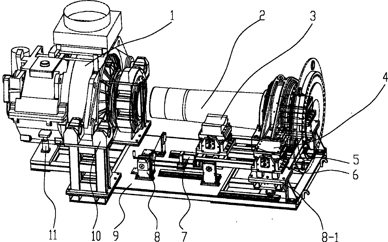
[0039] The core of the present invention is to provide an installation device, which can accurately assemble the shaft and the shaft hole, and can prevent the collision and damage of the shaft and the shaft hole during the installation process.

[0040] In order to enable those skilled in the art to better understand the technical solutions of the present invention, the present invention will be further described in detail below in conjunction with the accompanying drawings and specific embodiments.

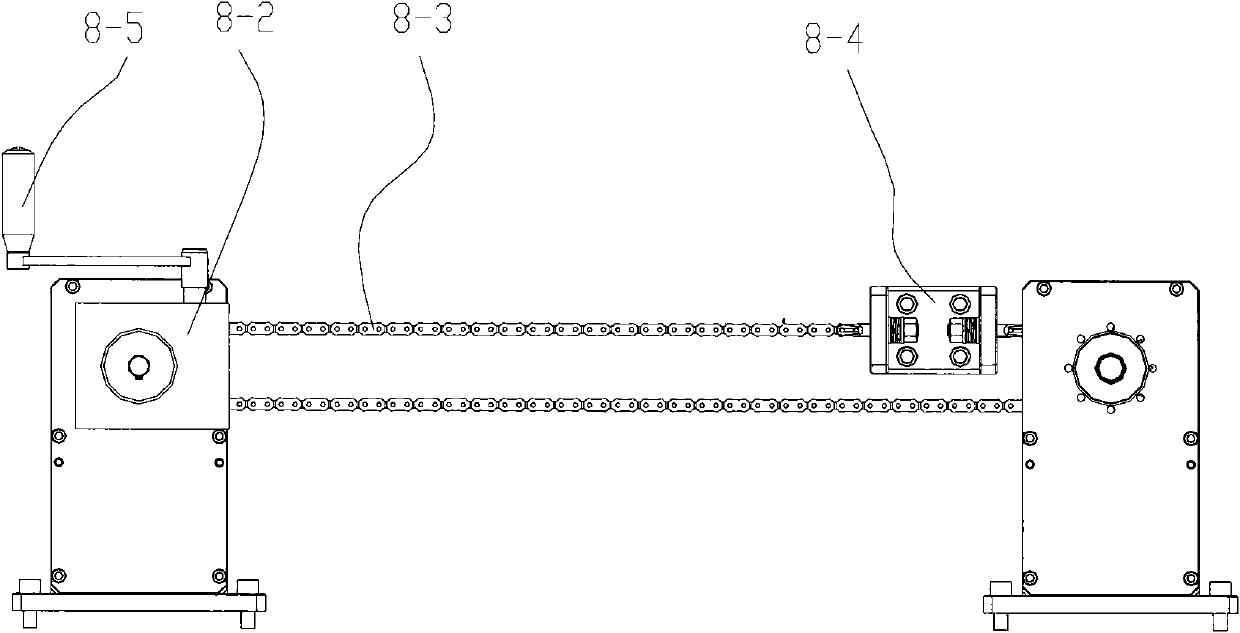
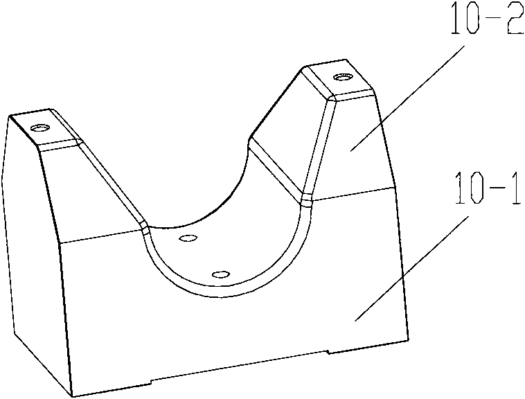
[0041] The installation equipment provided by the present invention is used to install the shaft in the shaft hole of the shaft hole. The installation equipment provided by the invention can be used for the assembly of all heavy shafts and shaft hole parts. 1. The assembly of the speed increaser is taken as an example to introduce the installation equipment provided by the present invention.

[0042] Please see figure 1 , figure 1 It is a structural schematic diagram of a speci...


PUM


Abstract

The invention discloses an installation device, relating to the technical field of mechanical assembly. The installation device is used for installing a shaft in a shaft hole of a shaft hole part and comprises a shaft hole part fixing device, a shaft fixing device and a support seat, wherein the shaft hole part fixing device is used for horizontally fixing the shaft hole part; the shaft fixing device is used for horizontally fixing the shaft; and the support seat is used for supporting the shaft hole part fixing device and the shaft fixing device; and the shaft hole center line of the shaft hole part fixed by the shaft hole part fixing device is aligned with the center line of the shaft fixed by the shaft fixing device. The shaft fixing device moves along the horizontal direction under the drive of a driving device. The installation device can accurately assemble the shaft and the shaft hole part and prevent collisions and gouges between the shaft and the shaft hole part in the installation process.

Description

technical field [0001] The invention relates to the technical field of mechanical assembly, in particular to a mounting device for mounting a shaft in a shaft hole of a shaft hole member. Background technique [0002] With the increasingly prominent social energy issues, climate issues, and environmental issues, the utilization of renewable resources has been paid more and more attention. Wind power has the advantages of abundant resources, good environmental benefits, high level of industrialization, and relatively low cost of power generation, and has become an important way to utilize renewable resources. [0003] A wind turbine is a power machine that converts wind energy into mechanical energy. The wind turbine uses wind power to drive the blades of the wind wheel to rotate, and then increases the speed of rotation through a speed increaser to drive the generator to generate electricity. [0004] A wind turbine usually includes a wind rotor, a main shaft, a gearbox, a ...

Claims


Application Information

Patent Timeline
IPC IPC(8): B23P19/04B23P19/10
Inventor 魏振山陈海澜
Owner SANY ELECTRIC CO LTD
Why Eureka
Try Eureka