Pneumatic slip shaft-based winding tension and rotation speed control method

A winding tension and speed control technology, applied in the direction of winding strip, thin material handling, transportation and packaging, etc., can solve the problems of no slip axis coordinated control, no dynamic compensation control of the dynamic process of speed up and down, and short life. , to achieve the effect of simple, easy and stable control compensation control

Active Publication Date: 2010-12-08
南通恒力重工机械有限公司
View PDF5 Cites 6 Cited by
  • Summary
  • Abstract
  • Description
  • Claims
  • Application Information

AI Technical Summary

Problems solved by technology

At present, the commonly used air control slip shaft winding tension control method adopts the method that the air intake air pressure of the air control slip shaft increases linearly with the increase of the winding diameter. The dynamic process is dynamically compensated and controlled; the second is that the winding inertia is not compensated and controlled; the third is that the speed

Method used


Image

  • Pneumatic slip shaft-based winding tension and rotation speed control method
  • Pneumatic slip shaft-based winding tension and rotation speed control method
  • Pneumatic slip shaft-based winding tension and rotation speed control method

Examples


Embodiment Construction

[0027] The specific steps of the winding tension and speed control method based on the air-controlled slip shaft are as follows:

[0028] Step a calculates the winding radius R (unit: m) according to the strip thickness and winding length;

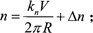
[0029] Step b calculates the speed n of the air-controlled slip shaft (unit: r / s);

[0030] Step c calculates the dynamic acceleration (decrease) speed of strip conveying (Unit: m / s 2 );

[0031] Step d calculates the input air pressure P (unit: MPa) of the air control slip shaft;

[0032] In step e, the obtained input air pressure P signal is input to the air-controlled slip shaft, and the speed n signal of the air-controlled slip shaft is input to the drive motor driver of the slip shaft, so as to realize the coordinated control of winding tension and speed.

[0033] The winding radius R described in the step a has a functional relationship R=r(h, L) with the strip thickness h (unit: m) and the winding length L (unit: m), which is e...


PUM


Abstract

The invention relates to a pneumatic slip shaft-based winding tension and rotation speed control method. The conventional control method lacks dynamic compensation control of an acceleration and deceleration dynamic process, compensation control of winding inertia and coordinate control of the rotation speed of a slip shaft, and therefore, causes serious heating and short service life of the slip shaft. The method comprises: firstly, computing a winding radius and the rotation speed n of the pneumatic slip shaft according to the width and winding length of a strip; secondly, computing a dynamic acceleration of the transport of the strip and the input air pressure of the pneumatic slip shaft; and finally, inputting the obtained input air pressure signal to the pneumatic slip shaft and the rotation speed signal of the pneumatic slip shaft into a slip shaft transmission motor driver to realize the coordinate control of the winding tension and rotation speed. When the method of the invention is used, the smooth control of the static and dynamic winding tension and the compensation control of the winding inertia can be realized, the slip power consumption of the pneumatic slip shaft is reduced, and thus, the life of the pneumatic slip shaft is improved greatly.

Description

technical field [0001] The invention belongs to the field of industrial automation, and relates to a method for controlling winding tension and rotational speed based on an air-controlled slip shaft used in a strip cutting machine. Background technique [0002] The air-controlled slip shaft is a key new winding component in all kinds of modern strip slitting machines. The differential shaft is driven by an electric motor. By adjusting the air pressure input to the inner bladder of the air control slip shaft, the friction force between the slip ring and the felt is changed to realize the alignment of several coils wound on the same air control slip shaft. The tension control of the coils, the tension of the strip between the coils may be different due to the uneven thickness of the coils and the inconsistency of the initial coil diameter. The speed of each slip ring may be different to ensure the normal operation of multiple coils independent of each other on the same slip s...

Claims


Application Information

Patent Timeline
IPC IPC(8): B65H23/04B65H23/24
Inventor 陈德传卢玲
Owner 南通恒力重工机械有限公司
Why Eureka
Try Eureka