Liquid-floated pressure power energy output device
A technology of power energy and output device, applied in the field of hydraulic floating pressure power energy output device, can solve problems such as unsatisfactory utilization rate of efficiency, and achieve the effect of improving utilization rate
- Summary
- Abstract
- Description
- Claims
- Application Information
AI Technical Summary
Problems solved by technology
Method used
Image
Examples
Embodiment 1
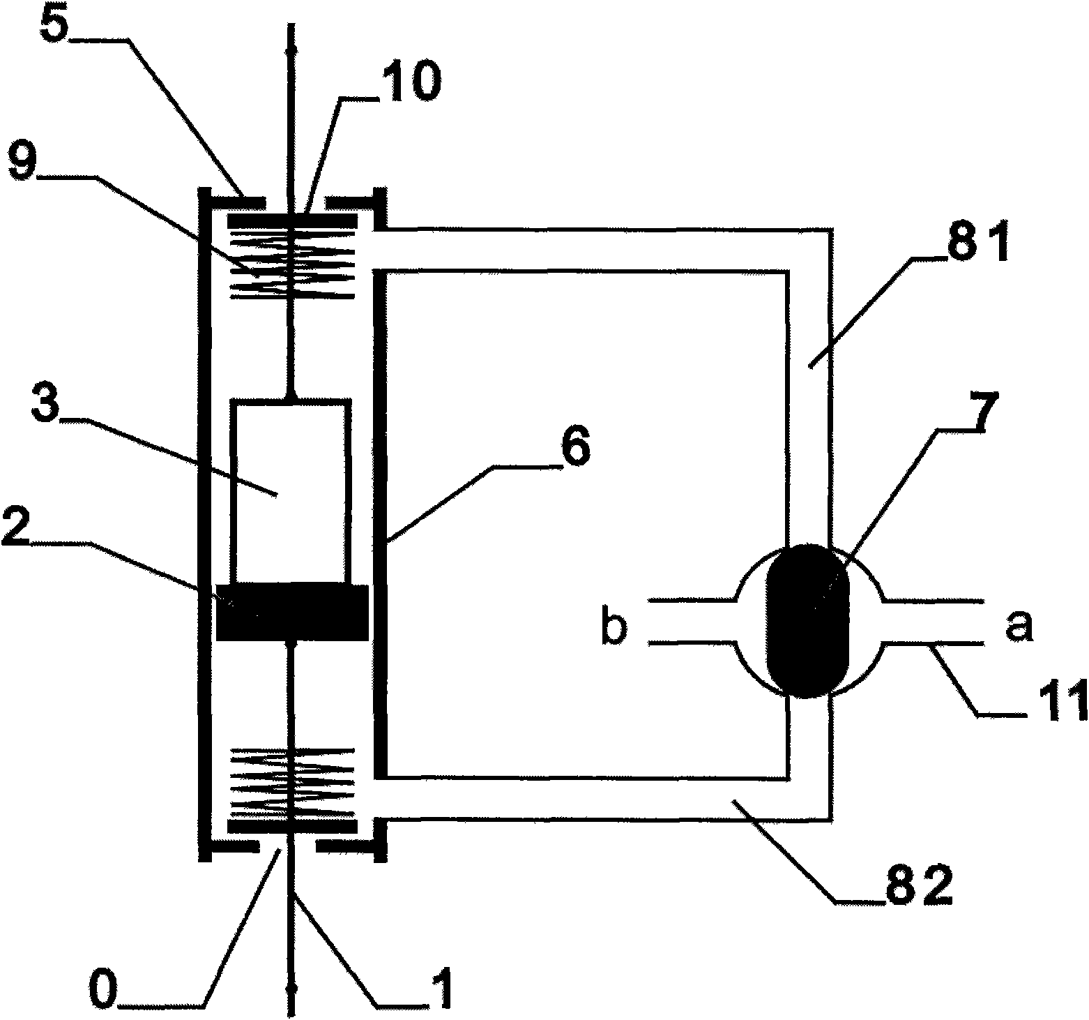
[0018] Embodiment 1 A liquid floating pressure power energy output device includes a float 4, a cylinder body 6 with a plug 5 with a hole up and down, and a control valve 7, wherein the control valve 7 is a four-way valve (see figure 1 ).
[0019] The float 4 is built in the cylinder body 6, and is composed of the piston 2 and the floating body 3 connected with the power output rod 1. The power output rod 1 passes through the hole on the plug 5; the cylinder body 6 and the control valve 7 pass through the communication pipe I 81 , and the communication pipe II 82 are connected, and the control valve 7 is provided with an external communication pipe 11 . The outer communication pipe 11 is provided with a liquid inlet a and a liquid outlet b.
[0020] When in use, after the device is filled with liquid, the control valve 7 is closed, and the water level of the liquid inlet a is higher than the water level of the liquid outlet b. This moment, the float 4 in the device is subjec...
Embodiment 2
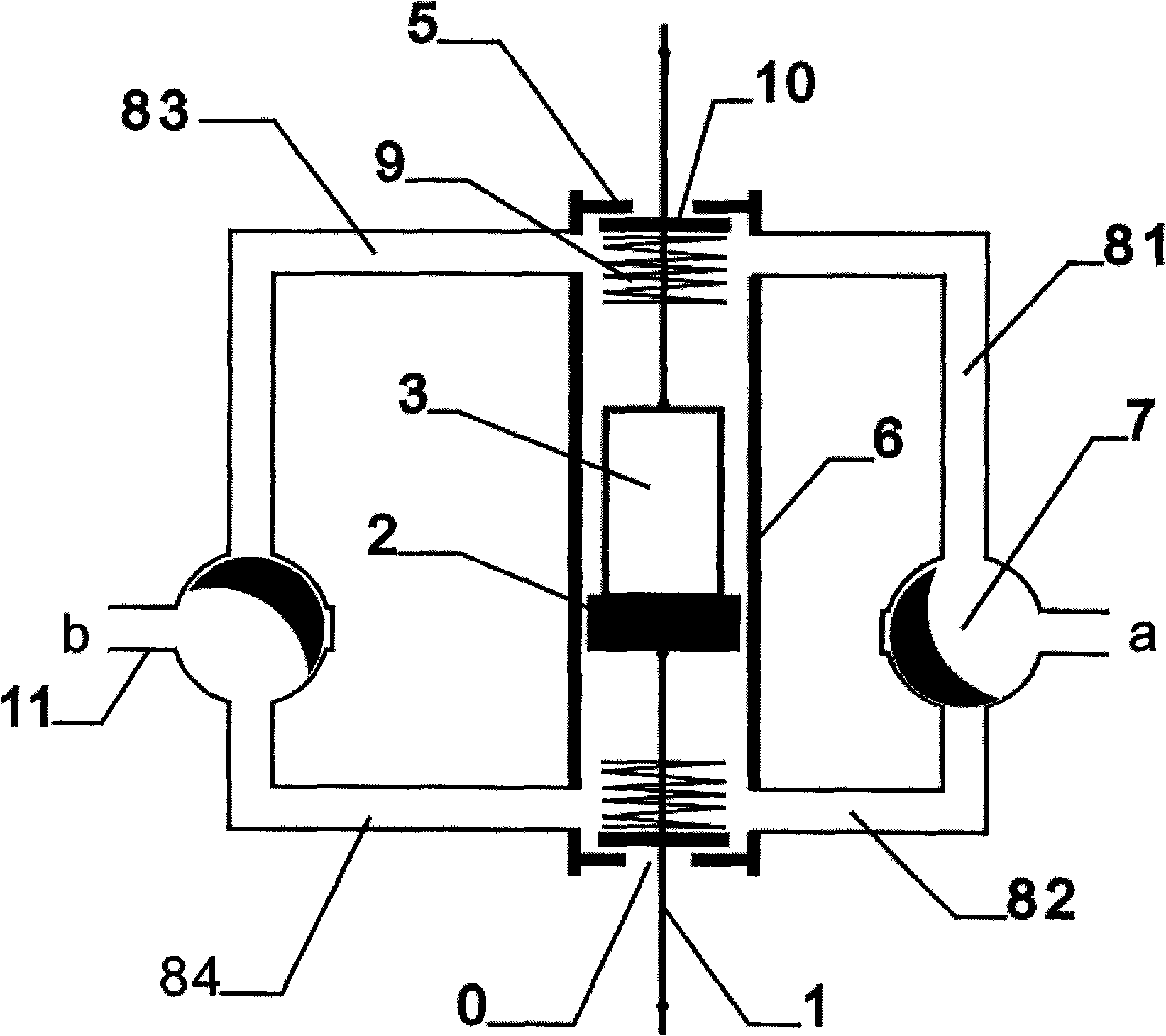
[0024] Embodiment 2 A liquid floating pressure power energy output device includes a float 4, a cylinder body 6 with a plug 5 with a hole up and down, and a control valve 7, wherein the control valve 7 is two three-way valves (see figure 2 ).
[0025] The float 4 is built in the cylinder body 6, and is composed of the piston 2 and the floating body 3 connected with the power output rod 1. The power output rod 1 passes through the hole on the plug 5; the cylinder body 6 and the control valve 7 pass through the communication pipe I 81 , connecting pipe II 82, connecting pipe III 83, and connecting pipe IV84 are connected, and the control valve 7 is provided with an external connecting pipe 11. The outer communication pipe 11 is provided with a liquid inlet a and a liquid outlet b.
[0026] When in use, after the device is filled with liquid, the control valve 7 is closed, and the water level of the liquid inlet a is higher than the water level of the liquid outlet b. This mom...
Embodiment 3
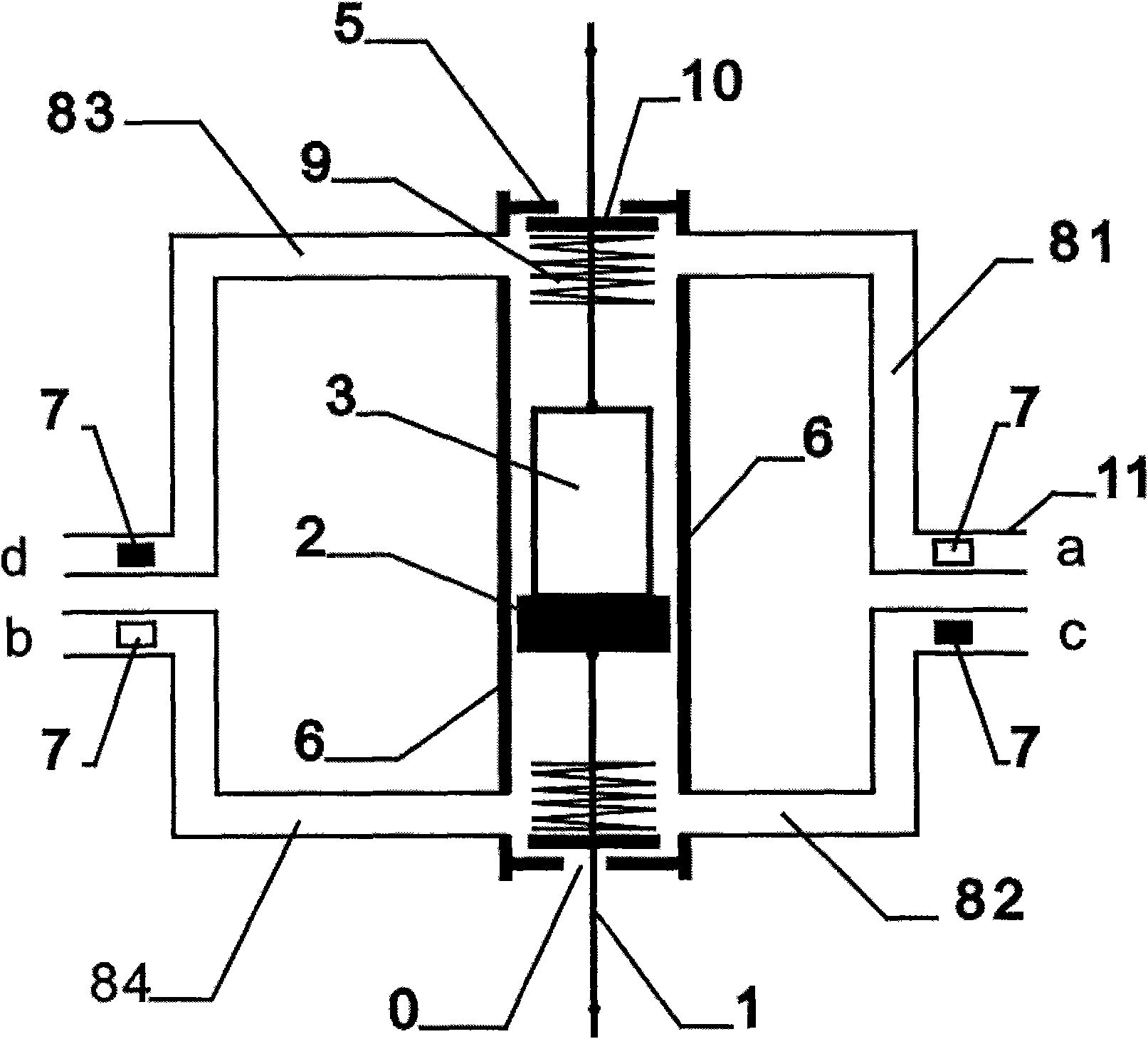
[0030] Embodiment 3 A liquid floating pressure power energy output device includes a float 4, a cylinder body 6 with a plug 5 with a hole up and down, and a control valve 7, wherein the control valve 7 is four two-way valves (see image 3 ).
[0031] The float 4 is built in the cylinder body 6, and is composed of the piston 2 and the floating body 3 connected with the power output rod 1. The power output rod 1 passes through the hole on the plug 5; the cylinder body 6 and the control valve 7 pass through the communication pipe I 81 , connecting pipe II 82, connecting pipe III 83, and connecting pipe IV84 are connected, and the control valve 7 is provided with an external connecting pipe 11. The outer connecting pipe 11 is provided with liquid inlets a, c, and liquid outlets b, d.
[0032] When in use, after the device is filled with liquid, the control valve 7 is closed, and the water levels of the liquid inlets a and c are higher than the water levels of the liquid outlets b...
PUM
 Abstract
Description
Claims
Application Information
 - R&D
- Intellectual Property
- Life Sciences
- Materials
- Tech Scout
- Unparalleled Data Quality
- Higher Quality Content
- 60% Fewer Hallucinations
Browse by: Latest US Patents, China's latest patents, Technical Efficacy Thesaurus, Application Domain, Technology Topic, Popular Technical Reports.
© 2025 PatSnap. All rights reserved.Legal|Privacy policy|Modern Slavery Act Transparency Statement|Sitemap|About US| Contact US: help@patsnap.com


