Power generation device

A technology for generating devices and power, applied in the field of power generating devices, can solve problems such as ineffective application and inability to use solar energy, and achieve the effects of simple structure, low cost, and easy maintenance

Inactive Publication Date: 2010-12-08
邱金和
View PDF0 Cites 2 Cited by
  • Summary
  • Abstract
  • Description
  • Claims
  • Application Information

AI Technical Summary

Problems solved by technology

[0003] However, no matter whether the above-mentioned methods of using "wind power", "solar power", "hydraulic power" or "geothermal" to generate energy are limited by "regional" restrictions; "Wind power" cannot be used to generate energy; similarly, in some areas where the climate is rainy all year round, "solar power" cannot be used; and "hydraulic power" and "geothermal power" only exist in some uniquely endowed areas
so it doesn't work well for every region of the world

Method used


Image

  • Power generation device
  • Power generation device
  • Power generation device

Examples


Embodiment Construction

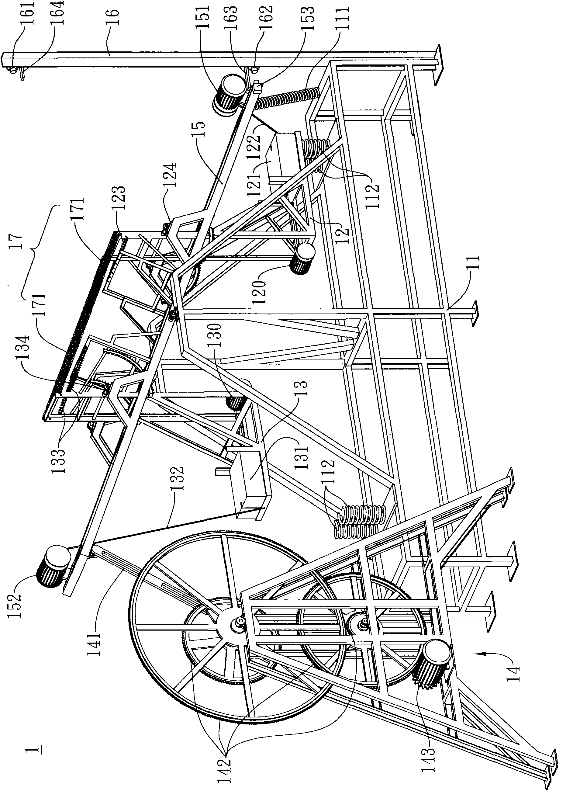
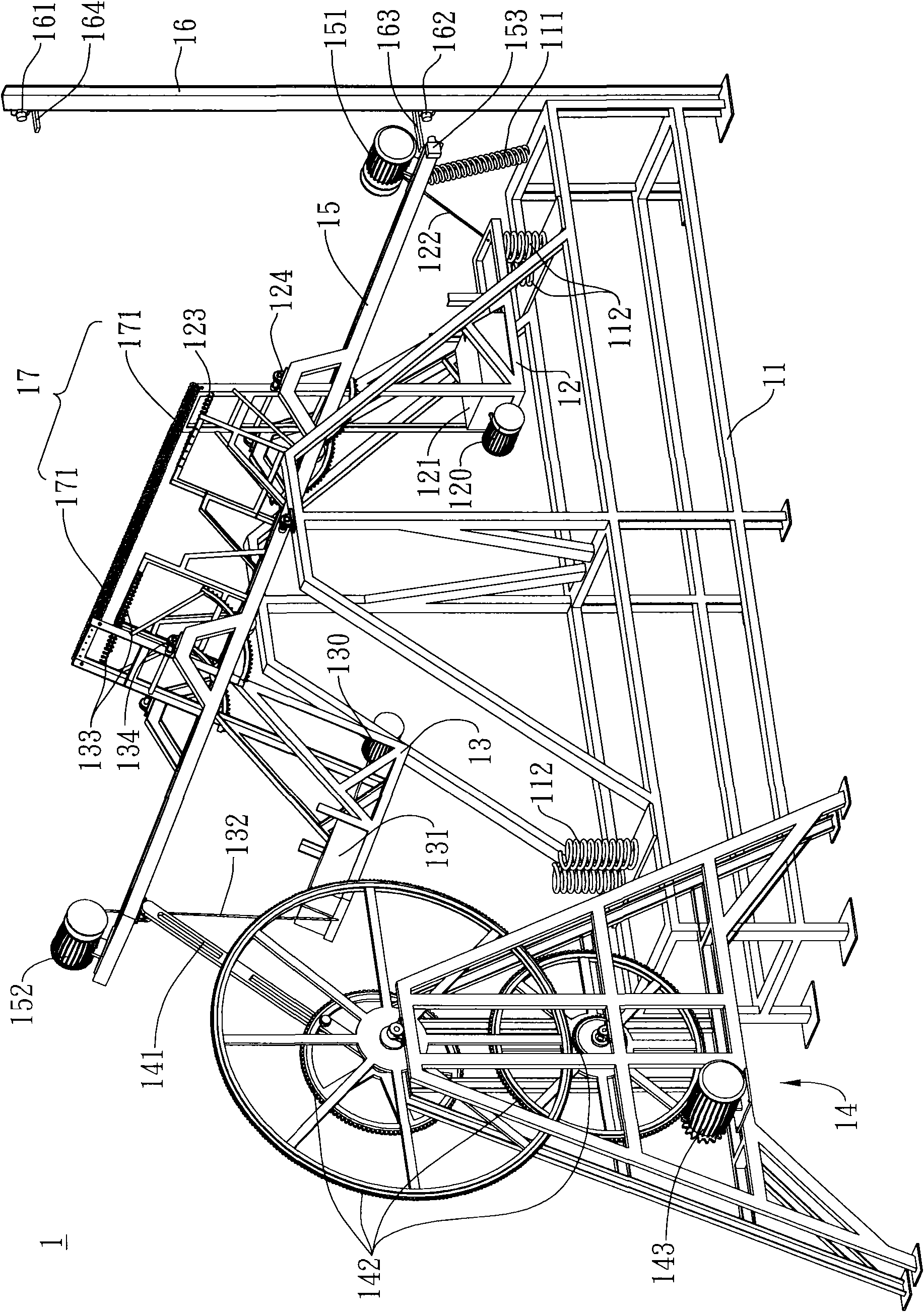
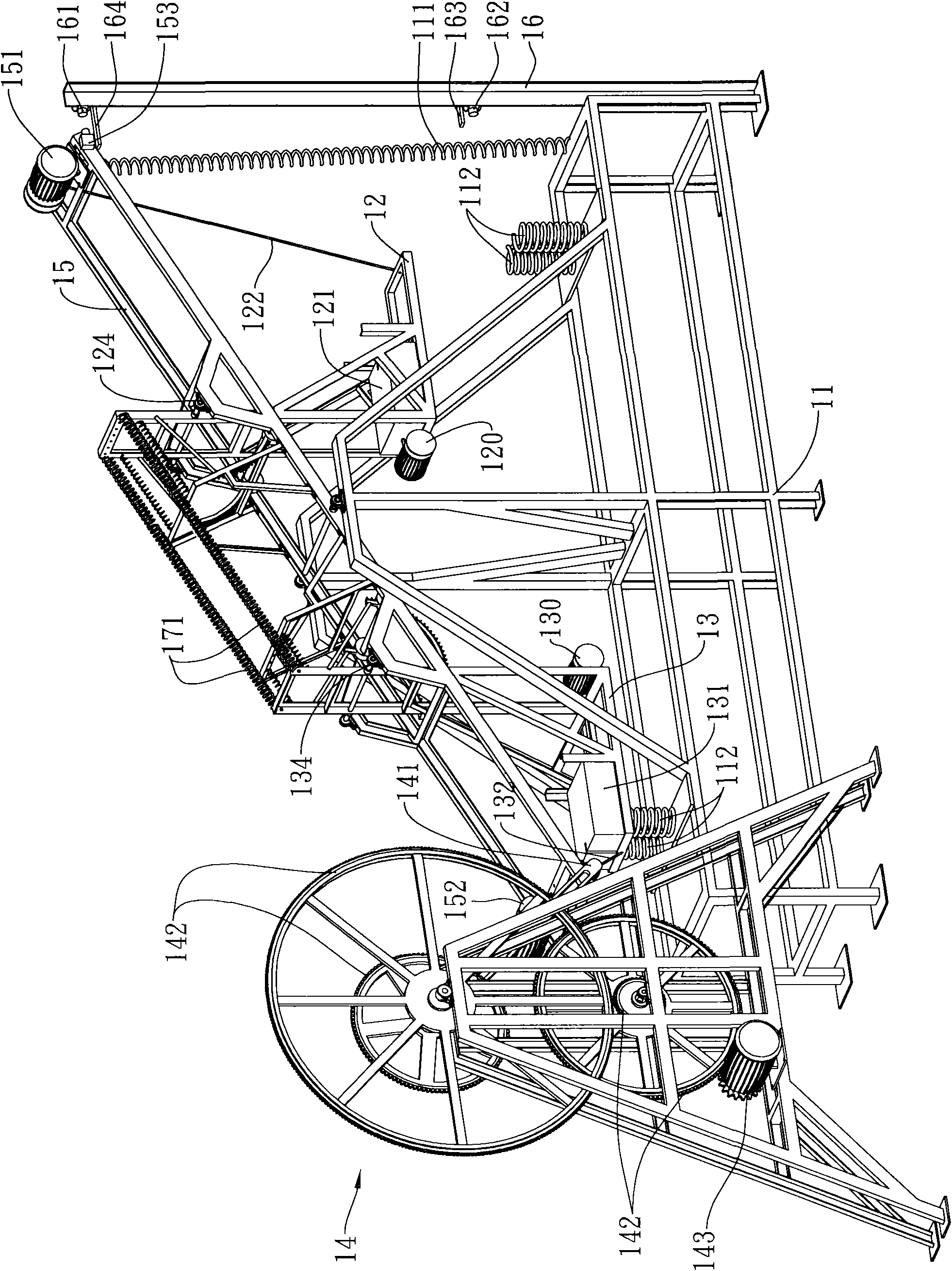
[0021] see figure 1 , the content of the drawing is an embodiment of the power generating device 1 of the present invention, which is composed of a base 11 , two L-shaped frames 12 , 13 and an energy collecting device 14 .

[0022] Described base 11 is provided with a lever 15, and lever 15 two ends are respectively provided with a motor 151,152, and described base 11 is respectively provided with spring 111, below lever 15 below and two L-shaped frame bodies 12,13 below. 112, a cylinder 16 is provided on one side of the base 11, a signal transmitter 161, 162 and an induction rod 163, 164 are provided at both ends of the cylinder 16, and the lever 15 is close to the cylinder 16 One end is provided with an induction controller 153 .

[0023] The two L-shaped frame bodies 12, 13 are relatively movable and pivotally connected to the two sides of the lever 15 near the central position, and the described L-shaped frame bodies 12, 13 are connected with the motors 151, 152 on the le...


PUM


Abstract

The invention relates to a power generation device. The device comprises a base, two L-shaped racks and an energy-collecting device, wherein the base is provided with a level, both ends of the level are separately provided with a motor; the two L-shaped racks are movably pivoted with the two sides of the level near the central position; the L-shaped racks are connected with the motors on the level to be pulled by the motors; the tail end of each L-shaped rack is provided with a weight and a motor, the weight is connected with the motor to be pulled by the motor and move left and right on the tail end of each L-shaped rack; after the front ends of the two L-shaped racks are connected through at least one connector, the front ends are linked with each other; and the energy-collecting device is connected with one end of the level to drive the energy-collecting device to operate and collect energy when the level swings.

Description

technical field [0001] The present invention relates to a power generating device, especially a power generating device which utilizes a motor to pull an L-shaped frame body to swing a lever, thereby driving an energy collecting device to run and store energy. The device has a simple structure, low cost and easy maintenance. Maintenance is easy. Background technique [0002] In recent years, as the earth's energy is about to face the crisis of energy depletion, countries around the world are constantly actively developing and utilizing "wind power", "solar power", "hydraulic power" or "geothermal" to generate electric energy, in order to Slow down the rate at which traditional energy sources are consumed. [0003] However, no matter whether the above-mentioned methods of using "wind power", "solar power", "hydraulic power" or "geothermal" to generate energy are limited by "regional" restrictions; for example, some areas have not strong wind all year round, namely "Wind pow...

Claims


Application Information

Patent Timeline
IPC IPC(8): F03G7/08F03G7/10
Inventor 邱金和
Owner 邱金和
Why Eureka
Try Eureka