Gain compensation device over temperature and method thereof

A gain compensation, temperature compensation technology, applied in amplifiers, high-frequency amplifiers, power amplifiers, etc., can solve problems such as inability to maintain constants

Inactive Publication Date: 2010-12-08
MEDIATEK INC
View PDF0 Cites 14 Cited by
  • Summary
  • Abstract
  • Description
  • Claims
  • Application Information

AI Technical Summary

Problems solved by technology

Therefore, the output signal S OUT Due to the influence of temperature changes, the power cannot be maintained as a constant (constant)

Method used


Image

  • Gain compensation device over temperature and method thereof
  • Gain compensation device over temperature and method thereof
  • Gain compensation device over temperature and method thereof

Examples


Embodiment Construction

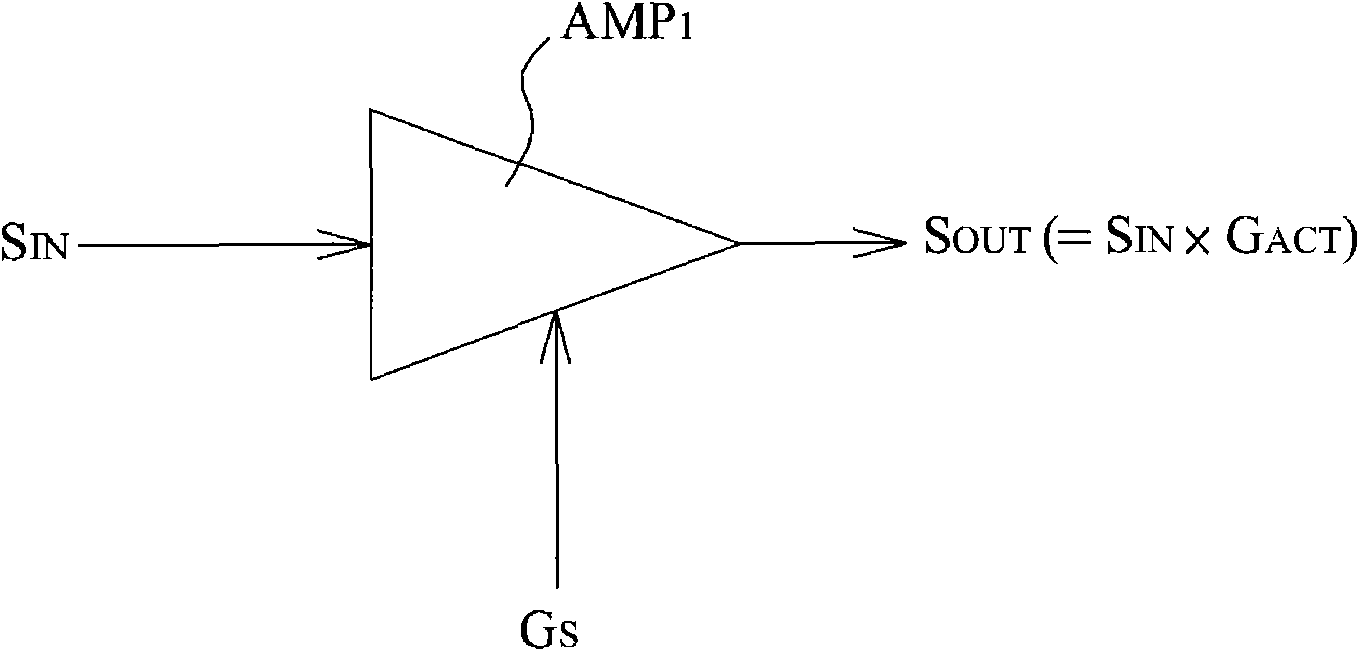
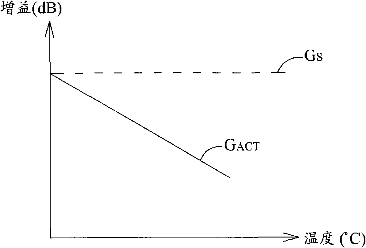
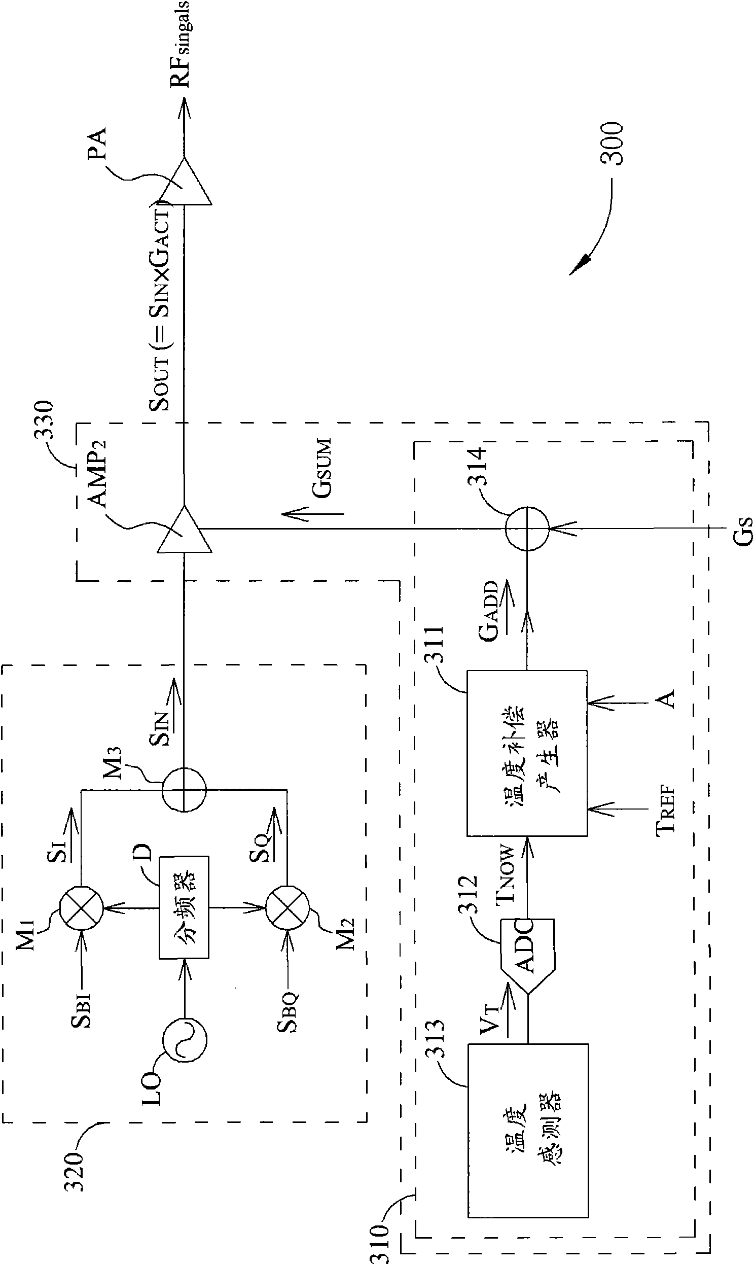
[0019] Please refer to image 3 and Figure 4 . image 3 Shown is a schematic diagram of a radio frequency (Radio Frequency, RF) transmitter 300 of the present invention. Figure 4 Shown is the amplifier AMP after using the gain compensation device 310 2 The actual gain G ACT schematic diagram. The radio frequency transmitter 300 includes a gain compensation device 310, a radio frequency module 320, an amplifier AMP 2 and power amplifier PA. The power amplifier PA according to the input signal S OUT Output radio frequency signal RF signal . Gain compensation device 310 and amplifier AMP 2 A temperature compensated amplification module 330 is formed. The temperature compensated amplification module 330 amplifies the received signal without being affected by temperature effect. In other words, in the temperature compensation amplifier module 330, the amplifier AMP 2 The gain compensation device 310 is used to eliminate the temperature effect of the radio frequency tr...


PUM


Abstract

The invention provides a gain compensation device over temperature and a method thereof. the gain compensation device for adjusting gain of an amplifier over temperature is disclosed. The gain of the amplifier is controlled by signals on a gain control end of the amplifier. The gain compensation device comprises a temperature compensation generator, an adder, and a temperature sensor. The temperature compensation generator is for generating an additional gain parameter according to a reference temperature, a current temperature, and a temperature coefficient. The adder comprises a first input end, coupled to the temperature compensation generator for receiving the additional gain parameter, a second input end for receiving a default gain parameter, and an output end coupled to the gain control end of the amplifier for outputting sum of the additional gain parameter and the default gain parameter. The temperature sensor is for providing the current temperature. The gain compensation device could make the actual gain keep constant owing to temperature change according to gain of temperature adjusting gain amplifier so as to provide great convenience.

Description

technical field [0001] The present invention relates to a temperature-related gain compensation device, and more particularly, to a gain compensation device and a method for compensating the gain of an amplifier according to temperature. Background technique [0002] Please refer to figure 1 . figure 1 Shown is a traditional amplifier AMP 1 schematic diagram. Amplifier AMP 1 The input terminal receives the input signal S IN , while the output of the amplifier AMP1 outputs the output signal S OUT . Such as figure 1 As shown in , according to the preset (default) gain parameter G S And set the amplifier AMP through the gain control terminal of the amplifier AMP1 1 The actual gain G ACT . Therefore, the input signal S can be amplified IN to generate the output signal S OUT , while in this setting the output signal S OUT The target power level (level) can be reached, where the input signal S IN with output signal S OUT The relationship between can be described as...

Claims


Application Information

Patent Timeline
Patent Type & Authority Applications(China)
IPC IPC(8): H03F1/30H03G1/04H04B1/04
CPCH03F3/189H03F2200/411H03F3/24H03F2200/447H03F2200/451
Inventor 李亦斌曾柏森
Owner MEDIATEK INC
Why Eureka
Try Eureka