Arc protection module

A technology for arc and protection switches, applied in the field of arc protection modules

Active Publication Date: 2010-12-08
SIEMENS AG
View PDF9 Cites 2 Cited by
  • Summary
  • Abstract
  • Description
  • Claims
  • Application Information

AI Technical Summary

Problems solved by technology

If a special arc protection switch is also added to this, this is associated with high expenditure

Method used


Image

  • Arc protection module
  • Arc protection module
  • Arc protection module

Examples


Embodiment Construction

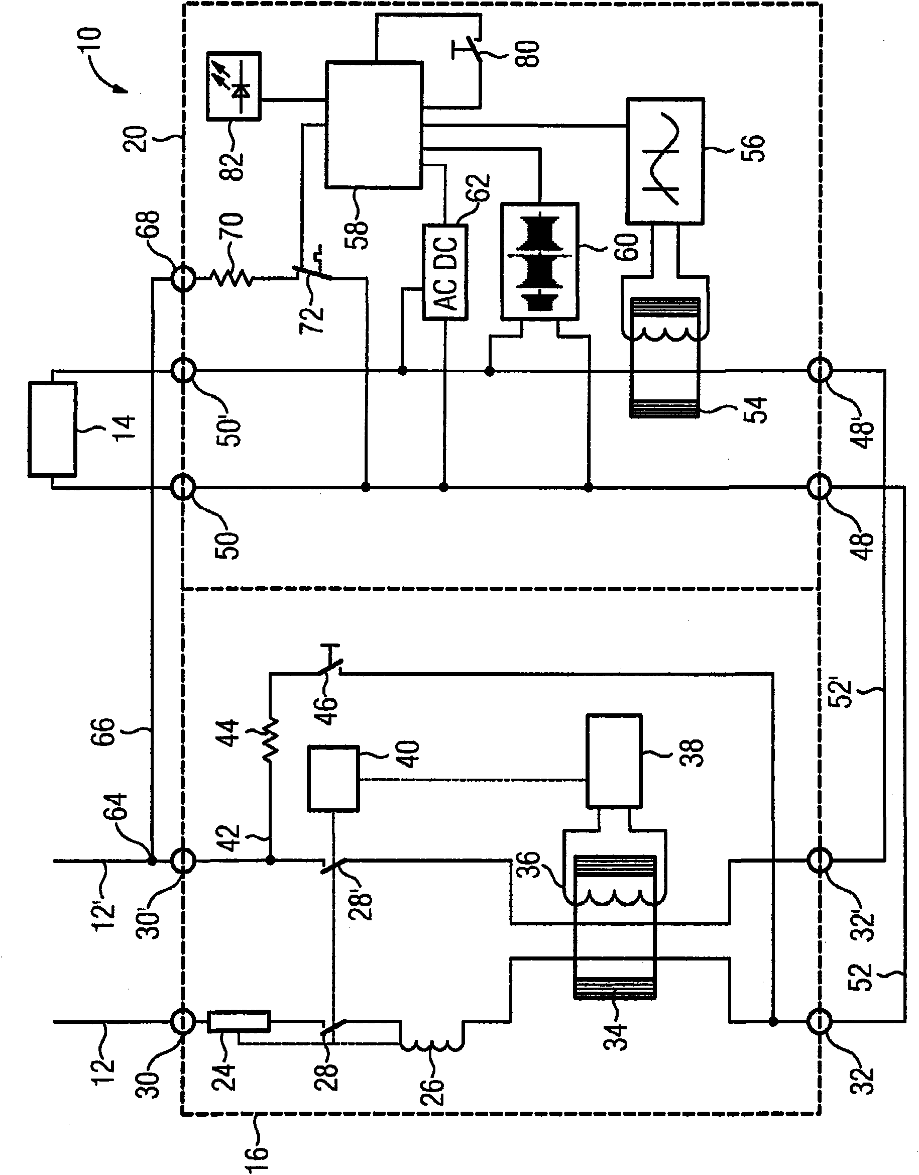
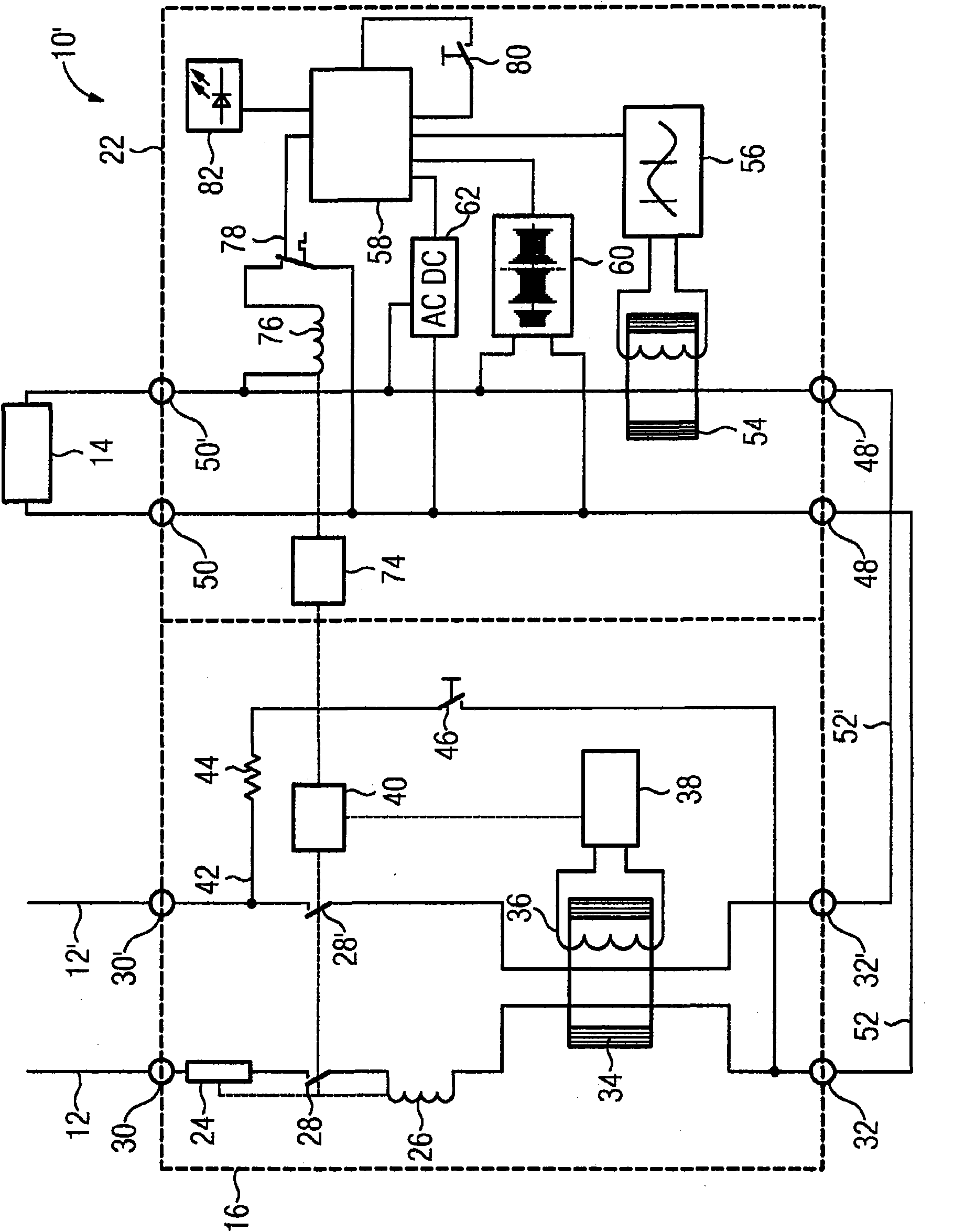
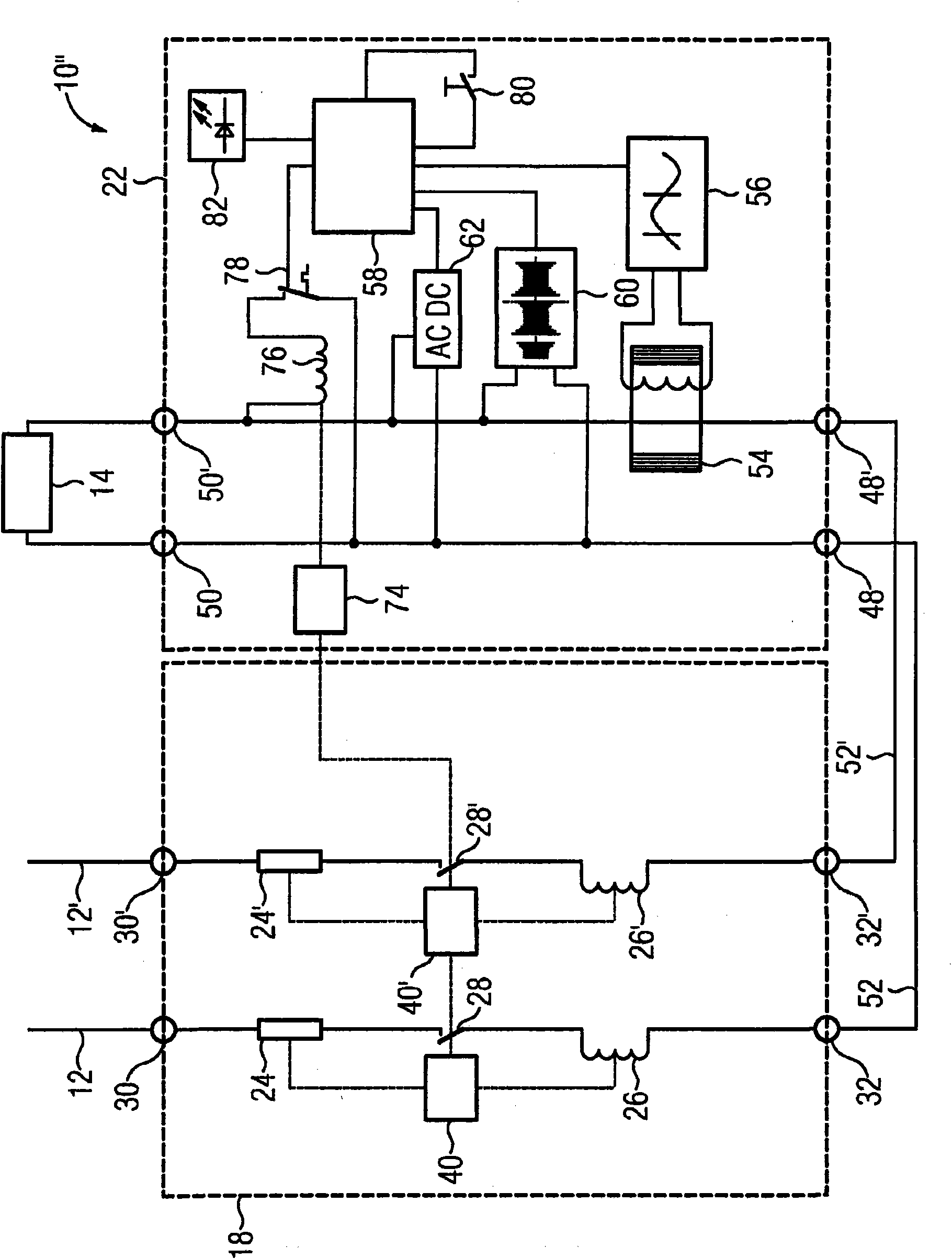
[0022] exist Figure 1 to Figure 3 The device 10, 10' or 10" shown in is a series circuit consisting of protective switches and modules, more precisely, these devices are arranged as part of a circuit so as to be able to exert influence on the current within the circuit. The device 10, 10' and 10" are coupled via lines 12, 12' to a voltage source (typically a power supply network). On the other side, a load is coupled, here a load 14 is shown symbolically. In the devices 10, 10' and 10", the protective switches used are known in principle, more precisely, the devices 10 and 10' are combined line protection switches and fault protection switches 16, while the device 10" is a simple Line protection switch 18. These protective switches 16 or 18 are part of the device 10, 10' or 10", since the modules cause the switching of the protective switch. In the device 10 a module 20 according to an embodiment of the prior art is used, while in the device 10' and 10″ using a module 22 a...


PUM


Abstract

In IEC technology, circuit breakers and residual current devices are used which have isolating contacts that interrupt the electric circuit in the event of excess current and a short-circuit current or a residual current. The aim of the invention is to provide a device which interrupts the electric circuit also when an arc is produced. To achieve this aim, a module (20, 22) comprises means for detecting whether an arc is produced in the electric circuit. The module (20, 22) does not have any isolating contacts of its own but means which cause the isolating contacts (28, 28') of a circuit breaker (16, 18) which is already arranged in the electric circuit to open. The opening of the contacts can be brought about electronically by producing an artificial residual current or via a mechanical coupling.

Description

technical field [0001] The invention relates to the protection of electric arcs occurring in electrical circuits. Background technique [0002] For example, arcs can occur in an electrical circuit if the light switch is defective and the distance between the two contacts of the light switch is so short that the current flow would be interrupted. Then, an arc is constructed exactly between the two contacts. In addition to arcs formed in batches in electrical circuits, arcs can also form between phase and neutral conductors of an electrical circuit. If an arc occurs, the temperature of the surrounding components rises and a burn develops. [0003] It is therefore expedient to provide a device with which protection against electric arcs is guaranteed. In the USA (where the so-called UL technology (Underwriters laboratories, standard with 110 V mains voltage) is used), such devices are even prescribed. There, arc protection switches are used, that is to say, arc protection s...

Claims


Application Information

Patent Timeline
Patent Type & Authority Applications(China)
IPC IPC(8): H01H83/14H02H1/00H02H3/33
CPCH01H2083/201H01H83/144H02H3/334H01H83/04H01H83/226H02H1/0015
Inventor H-J·休伯J-M·马特尔M·克利迈耶
Owner SIEMENS AG
Why Eureka
Try Eureka