Feed device for producing a secondary feed movement of the tool

A technology of feed movement and feed, which is applied in the direction of manufacturing tools, honing tools, metal processing, etc., and can solve the problem of too expensive equipment

Active Publication Date: 2018-11-09
GEHRING TECH
View PDF5 Cites 0 Cited by
  • Summary
  • Abstract
  • Description
  • Claims
  • Application Information

AI Technical Summary

Problems solved by technology

To produce such shapes, the devices known in the prior art are too expensive and can only be used with larger holes (D > 70 mm)

Method used


Image

  • Feed device for producing a secondary feed movement of the tool
  • Feed device for producing a secondary feed movement of the tool
  • Feed device for producing a secondary feed movement of the tool

Examples


Embodiment Construction

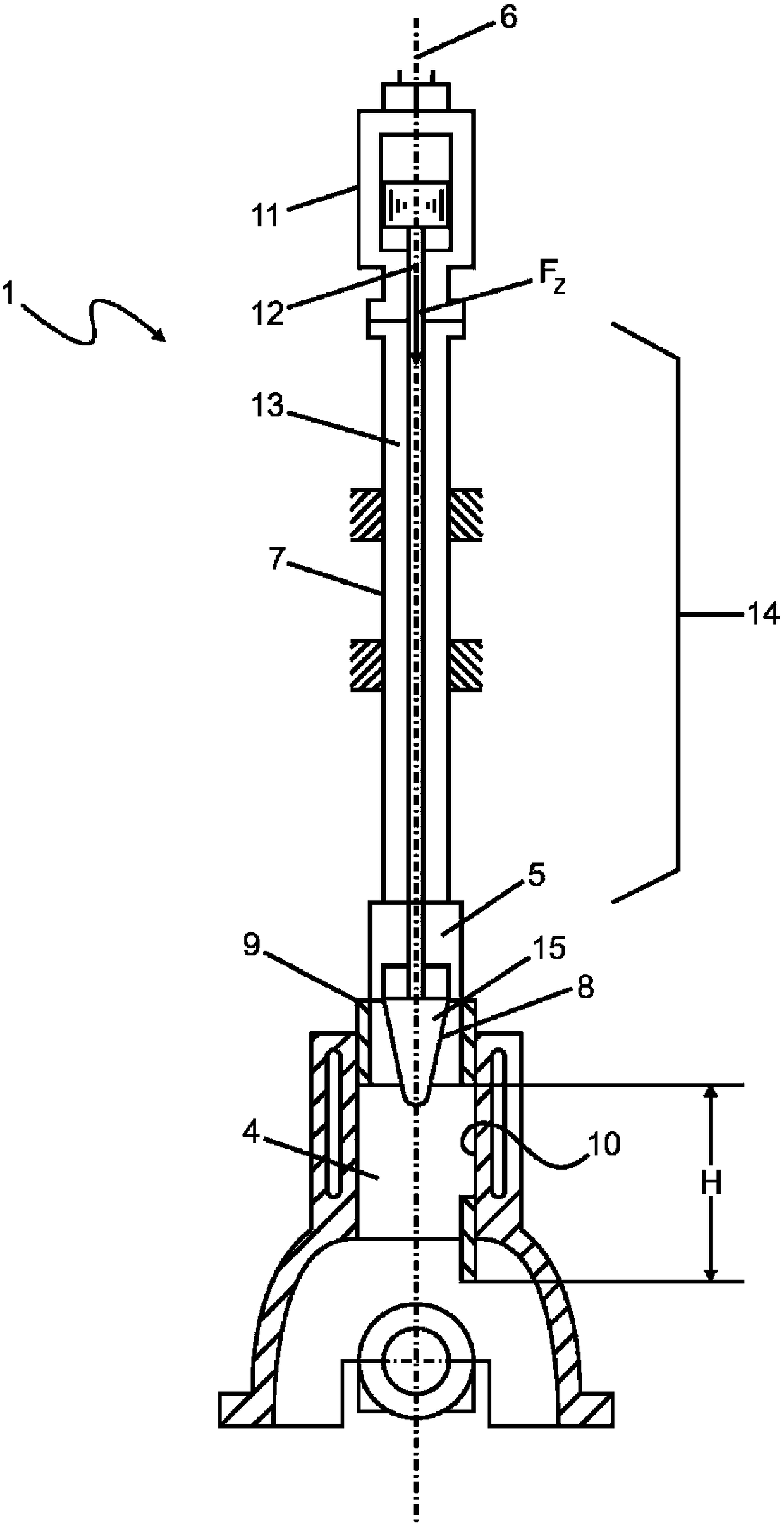
[0037] figure 1A prior art honing device 1 is shown. The honing device 1 produces a cylindrical bore 4 with a rotationally driven honing tool 5 in a known manner, wherein the honing tool 5 performs an oscillating lift movement in addition to the rotational movement.

[0038] The honing tool 5 is thus connected to a spindle 7 which is part of a not shown honing machine and which can be moved back and forth in the direction of the longitudinal axis of the bore or the inner surface 10 to be machined by eg hydraulic or electric lift drives. Furthermore, the spindle 7 is driven in rotation about its longitudinal axis 6 by a rotary drive (not shown) in a known manner. The honing tool 5 carries a machining tool 9 embodied as a honing stone, which can be fed radially outward from a hydraulically actuated feed and can be pressed against the inner surface 10 of the conical bore 4 . The feed device can also be actuated electrically via servo motors, for example. The hydraulic actuatio...


PUM


Abstract

The invention relates to a device and a method for producing a non-cylindrical inner surface (10) of a hole (4) with The processing tool (9) on the inner surface (10) of the . The device comprises a primary feed system (14) comprising an axially movable feed rod (13) for manipulating the machining tool (9) and where the primary force (FZ) Generated on at least one machining tool (9), by means of this primary force the at least one machining tool (9) can be fed radially onto the hole (4). The primary force (FZ) is dynamically superimposed on the secondary force generated by the secondary feed system (16), and the secondary feed system and the primary feed system (14) form an integral unit, or can be constructed modularly . The secondary feed system ( 16 ) is activated as a function of the current rotary and / or lift motion of the primary feed system ( 14 ), the current tool position, a specific feed force or at a specific point in time. Here, the tool has been enlarged by a one-stage feed.

Description

technical field [0001] The invention relates to a device for producing a non-cylindrical inner surface of a hole according to the preamble of claim 1 . Furthermore, the invention relates to a method for producing a non-cylindrical inner surface of a hole according to the preamble of claim 9 and a method for operating a non-cylindrical inner surface of a hole according to the preamble of claim 13 Control equipment for fixtures on the inner surface. Background technique [0002] The device for machining a hole described above preferably, but not exclusively, relates to a device for machining a hole by honing. [0003] The hole being honed must follow a predetermined geometry very precisely. Of course, some workpieces with honed bores become non-circular during installation (mechanical prestressing) and / or during operation due to forces or through temperature-dependent deformations. This shape change is a change from an ideal cylindrical shape. In order to compensate such s...

Claims


Application Information

Patent Timeline
Patent Type & Authority Patents(China)
IPC IPC(8): B24B33/02B24B33/08B23B29/034
CPCB24B33/02B23B29/03446B23B2260/108B24B33/088B23B29/03432
Inventor 安德里亚斯·韦恩斯曼纽尔·外博林格安德里亚斯·瓦格纳克劳斯·莉蒂
Owner GEHRING TECH
Why Eureka
Try Eureka