Vibrating table for centrifugal machine

A technology of vibrating table and centrifuge, which is applied in the direction of centrifuge, etc., can solve problems such as the displacement of moving parts of the vibrating table, and achieve the effect of simple control, low density and low cost

Inactive Publication Date: 2010-12-15
ZHEJIANG UNIV
View PDF3 Cites 6 Cited by
  • Summary
  • Abstract
  • Description
  • Claims
  • Application Information

AI Technical Summary

Problems solved by technology

[0004] In order to overcome the shortcomings of the existing vibrating table that cannot be directly used in a centrifugal environment due to the offset of the moving parts in the centrifugal environment, the present invention provides a vibration table that corrects the offset of the moving parts in the centrifugal environment and can be directly used in the centrifugal environment. centrifuge with shaker

Method used


Image

  • Vibrating table for centrifugal machine
  • Vibrating table for centrifugal machine
  • Vibrating table for centrifugal machine

Examples


Embodiment Construction

[0043] With reference to accompanying drawing, further illustrate the present invention:

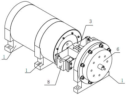
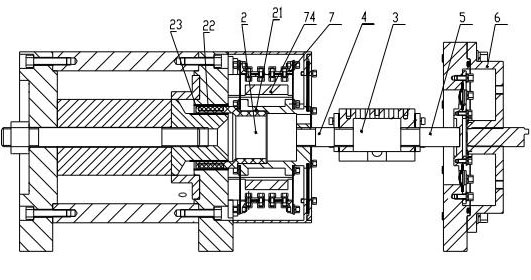
[0044] A vibrating table for a centrifuge, including a frame 1, the frame 1 is provided with a vibrating table moving coil 2 that generates vibrations and a test platform 3 for carrying workpieces to be tested, and the left end of the test platform 3 passes through the platform The push rod 4 is linked with the moving coil 2 of the vibrating table;

[0045] The right end of the test platform 3 is connected to a deviation-correcting mechanism 6 to prevent the vibrating table moving coil 2 from excessively deflecting in the axial direction through the deviation-correcting push rod 5;

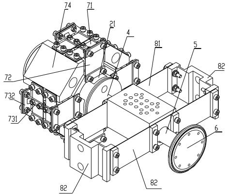
[0046] The upper periphery of the aluminum frame 21 of the moving coil of the vibrating table is provided with a support mechanism 7 that prevents the circumferential torsion or radial displacement of the moving coil.

[0047] The support mechanism 7 includes a hollow reed support 74 fixed to the frame 1, a...


PUM


Abstract

The invention relates to a vibrating table for a centrifugal machine, which comprises a stand. A vibrating table moving coil for generating vibrations and a test platform for a carrier belt to test workpieces are arranged on the stand, and the left end of the test platform is linked with the vibrating table moving coil through a platform push rod; the right end of the test platform is connected with a deviation correcting mechanism for preventing the vibrating table moving coil from excessively deviating on axial direction through a deviation correcting push rod; an aluminum frame of the vibrating table moving coil is provided with supporting mechanisms for preventing the moving coil from twisting or circumferentially rotating, convex edges are uniformly distributed on the aluminum frame, and one supporting mechanism is arranged between any two adjacent convex edges; each supporting mechanism comprises an axial spring installed on the convex edges along the axial direction of the moving coil and a radial spring installed along the radial direction of the moving coil to connect the axial spring and the aluminum frame; and the right end and the left end of the aluminum frame are both provided with radial springs. The invention has the advantages of correcting the deviation of a moving part in centrifugation environment and being directly used for the centrifugal machine.

Description

technical field [0001] The invention relates to a vibrating table, in particular to a vibrating table which can be directly applied in a centrifugal environment. technical background [0002] The rapid development of my country's aerospace industry puts forward higher and higher requirements for the reliability of aerospace devices. The life of various components inside the space device is directly related to the reliability of the space device. It is of great theoretical and practical significance to conduct reliability accelerated environmental tests on these components. However, the single-parameter environmental test cannot fully simulate the working environment of aerospace device components. In order to improve the accuracy of the environmental test, it is necessary to build a multi-parameter compound environmental accelerated test system, and to study the compound environmental test and the coupling between various environmental factors. [0003] The combination of...

Claims


Application Information

Patent Timeline
Patent Type & Authority Applications(China)
IPC IPC(8): B04B7/00
Inventor 何闻王春宇沈润杰贾叔仕
Owner ZHEJIANG UNIV
Why Eureka
Try Eureka