Automatic pipe cutting and chamfering device

An automatic cutting and chamfering device technology, which is applied in the field of mechanical processing, can solve the problems of uneven chamfering, high cost, and low efficiency, and achieve the effects of high automation, high processing efficiency, simple structure, and fast speed

Inactive Publication Date: 2010-12-15
NORTHWESTERN POLYTECHNICAL UNIV
View PDF7 Cites 18 Cited by
  • Summary
  • Abstract
  • Description
  • Claims
  • Application Information

AI Technical Summary

Problems solved by technology

[0005] In order to overcome the shortcomings existing in the prior art that the cutting and chamfering of pipes are processed separately, or that both ends of the chamfering cannot be performed at the same time, or the process is complicated, the cost is high, or the efficiency is low and the chamfering is uneven. An automatic pipe cutting and chamfering device

Method used


Image

  • Automatic pipe cutting and chamfering device
  • Automatic pipe cutting and chamfering device
  • Automatic pipe cutting and chamfering device

Examples


Embodiment Construction

[0043] The present invention is described in detail below in conjunction with accompanying drawing

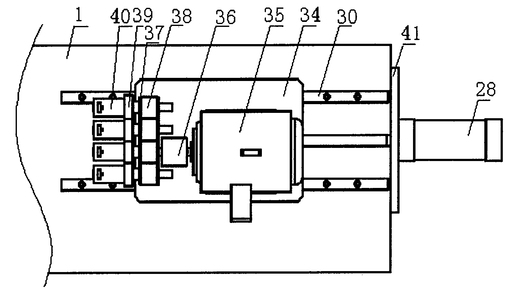
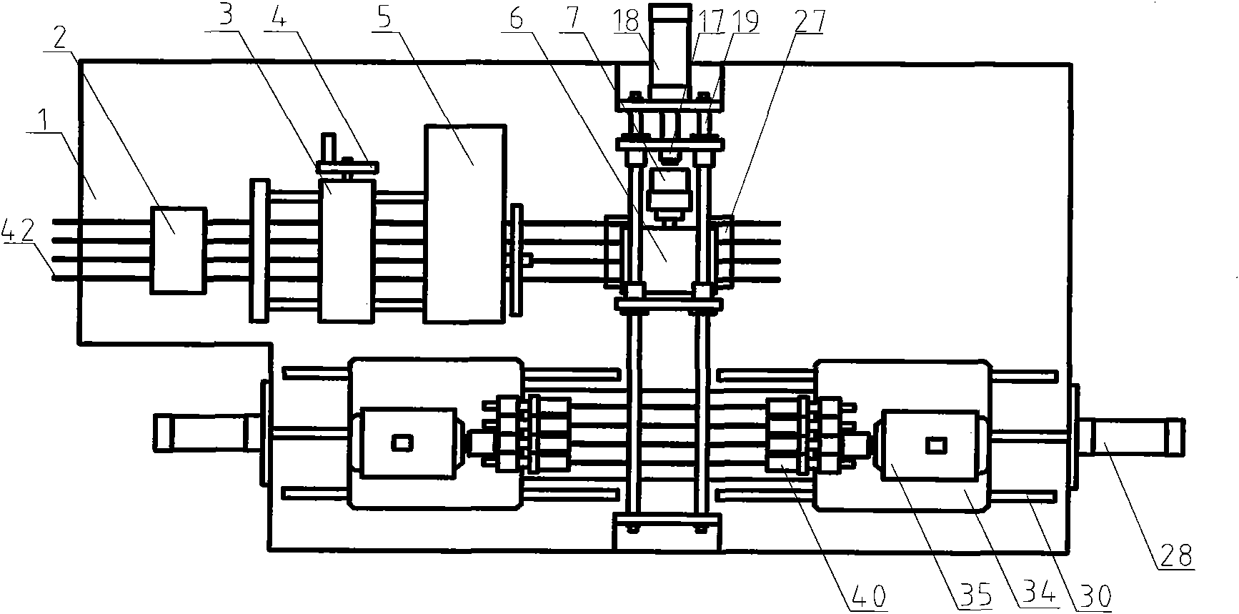
[0044] Such as figure 1As shown, an automatic pipe cutting and chamfering device includes a frame 1, a straightening mechanism 2, a handwheel sliding mechanism 3, a handwheel 4, a cutting mechanism 5, a pushing mechanism and a chamfering mechanism. Wherein straightening mechanism 2, handwheel sliding mechanism 3, handwheel 4 and cutting mechanism 5 all adopt prior art, are installed on the frame 1 successively; Pushing mechanism is positioned at cutting mechanism 5 one ends, and clamper in pushing mechanism The center line of the pipe material clamping groove on the top coincides with the center line of the pipe material 42 placed in the cutting mechanism 5 . The chamfering mechanism is located on one side of the cutting mechanism 5, parallel to the cutting mechanism 5, and perpendicular to the pushing mechanism.

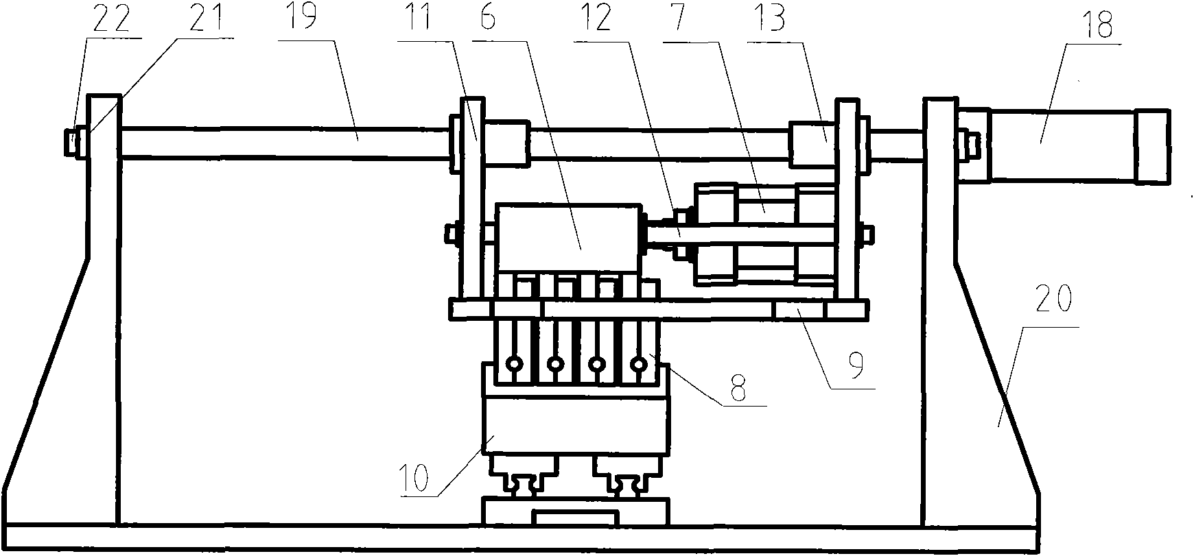
[0045] Such as figure 2 As shown, the pushing mechanism inc...


PUM


Abstract

An automatic pipe cutting and chamfering device is characterized in that a straightening mechanism, a hand wheel slipping mechanism, a hand wheel and a cutting mechanism are installed on a rack in sequence; a push mechanism is positioned at one end of the cutting mechanism and the center line of a pipe clamping groove on a clamp in the push mechanism coincides with the center of a pipe in the cutting mechanism; and a chamfering mechanism is positioned at one side of the cutting mechanism, is parallel with the cutting mechanism and is vertical to the push mechanism. After the pipe is cut by the cutting mechanism, the pipe is clamped and fixed by the clamp and the push mechanism pushes the clamp and the pipe to a chamfering station to be chamfered. The device integrates the functions of pipe straightening, cutting and chamfering, ensures the pipe to be directly chamfered after being cut, improves the degree of automation and efficiency of pipe processing and ensures uniform chamfers. The device provided by the invention has simple structure, lowers the processing cost and is convenient to operate.

Description

technical field [0001] The invention relates to the field of mechanical processing, in particular to a pipe processing device. Background technique [0002] In the patent with the publication number CN2673592, a pipe cutting and chamfering machine is disclosed, which is characterized in that the chamfering device and the cutting machine are on the same frame, and the translation mechanism is fixed on the pipe fixing frame, and the translation mechanism consists of a gear and a rack Cooperate to form, the gear is connected with the manual running wheel. The translation mechanism is driven by the rack and pinion transmission, so that one end of the pipe can be chamfered after the pipe is cut. [0003] In the patent with the publication number CN201361786, a special equipment for pipe cutting and chamfering is disclosed, which is characterized in that two sets of mutually perpendicular guide rails are arranged on the horizontal end surface of the frame, that is, the A guide ra...

Claims


Application Information

Patent Timeline
IPC IPC(8): B23P23/00B23Q3/06B23Q7/00
Inventor 杨旭东谭小群杨乾乾乔良沈宏华
Owner NORTHWESTERN POLYTECHNICAL UNIV
Why Eureka
Try Eureka