
Power meter calibrating system and power meter calibrating method for intelligent electric meter

A smart meter and meter calibration technology, applied in the direction of electrical signal transmission system, signal transmission system, measurement of electrical variables, etc., can solve the problem of low measurement accuracy, inability to guarantee the linearity of small current point error ammeter, weak manganese copper sampling signal, etc. question

Active Publication Date: 2010-12-15
ZHUHAI ZHONGHUI MICROELECTRONICS
View PDF7 Cites 22 Cited by
  • Summary
  • Abstract
  • Description
  • Claims
  • Application Information

AI Technical Summary

Problems solved by technology

[0003] Taking the meter based on manganese-copper sampling as an example, due to the consideration of power loss and system heating, the value of the manganese-copper resistance is generally micro-ohm level, so the current loop input signal to the AD sampling terminal is also relatively small (the small current point is only Tens of microamplitudes), such a weak signal is easily affected by external signals, resulting in large power errors at small current points. These effects come from the parasitic capacitance on the current sampling circuit, the magnetic flux leakage interference of the transformer, and the interference of the power supply circuit. If the DC offset introduced by these signal loops cannot be effectively processed, the accuracy of the small current point error and the linearity of the meter in the entire measurement range cannot be guaranteed.
[0004] The electric meter industry has always believed that the weak manganese-copper sampling signal leads to low measurement accuracy, so that the manganese-copper sampling scheme has always remained in single-phase meters for residential use and three-phase active meters with low precision requirements.

Method used


Image

  • Power meter calibrating system and power meter calibrating method for intelligent electric meter
  • Power meter calibrating system and power meter calibrating method for intelligent electric meter
  • Power meter calibrating system and power meter calibrating method for intelligent electric meter

Examples


Embodiment Construction

[0016] (Formula 1)

[0017] in: is the real-time power value measured by the smart meter, is the power gain, is the power bias, is the original value of the power after the current-voltage dot product.

[0018] and calculate the power error using the following Equation 2, where: is the real-time power error of the meter relative to the meter calibration station, is the real-time power value measured by the smart meter, It is the standard power value of the calibration table.

[0019] (Formula 2)

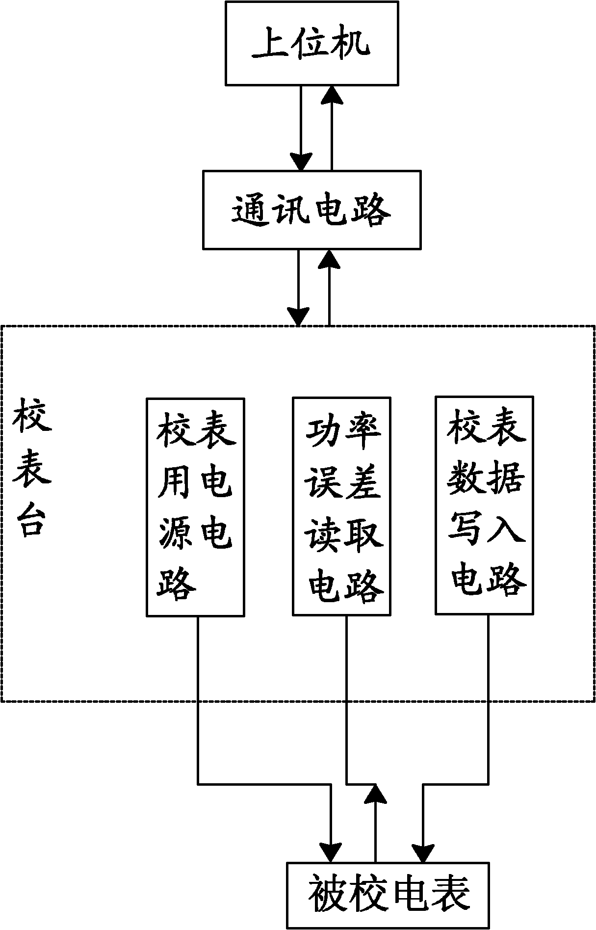
[0020] In order to realize the smart meter power calibration method of the present invention, this embodiment first provides a smart meter power calibration system, see figure 1 , the system includes a meter calibration station, a host computer and a communication circuit connecting them; the meter calibration station provides a power supply circuit for meter calibration, a power error reading circuit and a meter calibration da...


PUM


Abstract

The invention aims to provide a power meter calibrating system and a power meter calibrating method for an intelligent electric meter. The power accuracy of a manganin sampling-based intelligent electric meter is improved in a mode of meter calibrating to ensure the high efficiency and consistency of quantity production. The meter calibrating system comprises a meter calibrating platform, an upper computer and a communication circuit connected with the meter calibrating platform and the upper computer, wherein the meter calibrating platform is provided with a power supply circuit for meter calibrating, a power error reading circuit and a meter calibrating data writing circuit. In the meter calibrating method, by adopting the meter calibrating scheme of two-point mixing, namely a real-time error value of the intelligent electric meter is read quickly under a heavy current point, and a real-time power value is read stably under a low current point, two meter calibrating parameters of a power gain value and a power biasing value of the electric meter are obtained through calculation by a corresponding algorithm, and the two parameters are written into the electric meter by utilizing meter calibrating data.

Description

technical field [0001] The invention relates to the field of electric energy measurement, in particular to a scheme for calibrating the power of an intelligent electric meter based on manganin-copper sampling. Background technique [0002] Driven by the popular smart grid all over the world, how to improve the measurement accuracy of smart meters has become a common goal in the electric energy measurement industry. [0003] Taking the meter based on manganese-copper sampling as an example, due to the consideration of power loss and system heating, the value of the manganese-copper resistance is generally micro-ohm level, so the current loop input signal to the AD sampling terminal is also relatively small (the small current point is only Tens of microamplitudes), such a weak signal is easily affected by external signals, resulting in large power errors at small current points. These effects come from the parasitic capacitance on the current sampling circuit, the magnetic flu...

Claims


Application Information

Patent Timeline
Patent Type & Authority Applications(China)
IPC IPC(8): G01R35/04G08C19/00
Inventor 任智仁周宣康希郭如
Owner ZHUHAI ZHONGHUI MICROELECTRONICS
Learn More