Terminal box

A terminal box and box body technology, which is applied in the direction of non-electric variable control, instruments, guards/shutters to prevent contact with contacts, etc., can solve the problem of lack of control, lack of cooling effect, and inability to meet the operation of intelligent electronic equipment Requirements and other issues, to achieve the effect of intelligentization, easy temperature control and dehumidification

Inactive Publication Date: 2010-12-15
GUANGZHOU ELECTRIC POWER DESIGN INST +1
View PDF5 Cites 18 Cited by
  • Summary
  • Abstract
  • Description
  • Claims
  • Application Information

AI Technical Summary

Problems solved by technology

[0004] (1) Because there are ventilation louver holes on the wall of the cabinet, on the one hand, the temperature and humidity in the cabinet are greatly affected by the environment and cannot be controlled; on the other hand, dust, moisture, corrosive gases, and even some insects , Small animals will enter the box through the ventilation louver holes, affecting the normal operation of the electrical components in the box;
[0005] (2) There are the following problems in improving the working environment in the box by heating up the heater and convective replacement of the air inside and outside the box: ①The heating of the heater only temporarily reduces the humidity in the box, and the moisture in the air in the box does not When the ambient temperature drops, the water vapor in the air will condense and adhere to the surface of electrical components, burying hidden dangers for the safe operation of electrical equipment; ②The temperature and humidity of the air outside the box are not certain Yes, it may be high temperature and high humidity. After the replacement, the condition inside the box will become worse and cannot meet the operating requirements of smart electronic devices; If the temperature is lowered, it is easy to block the air outlet, so that the air inside and outside the box cannot circulate, which not only fails to achieve the cooling effect, but also causes the temperature inside the box to rise in turn.

Method used


Image

  • Terminal box
  • Terminal box
  • Terminal box

Examples


Embodiment Construction

[0030] Embodiments of the present invention are described in detail below in conjunction with accompanying drawings:

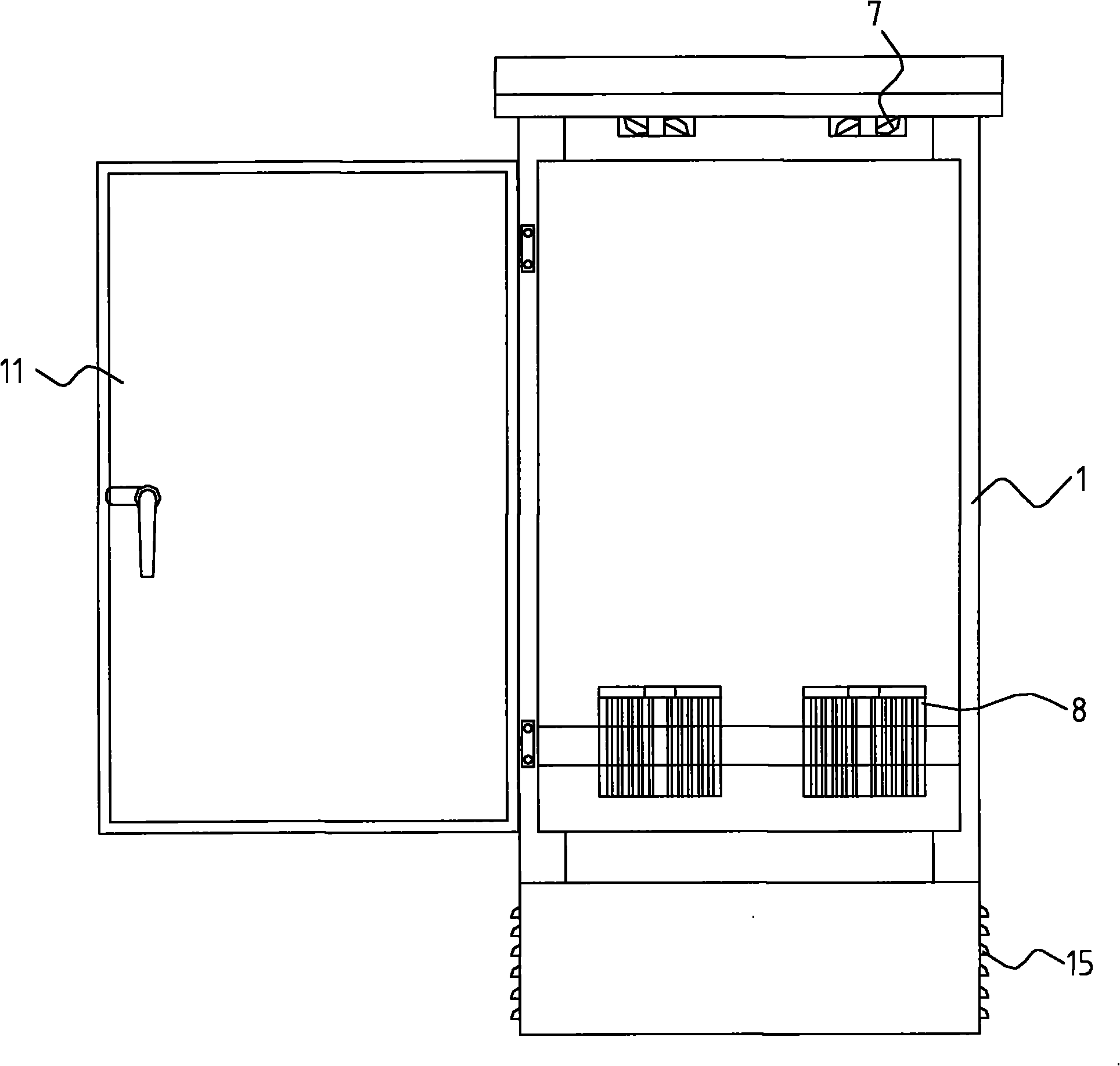
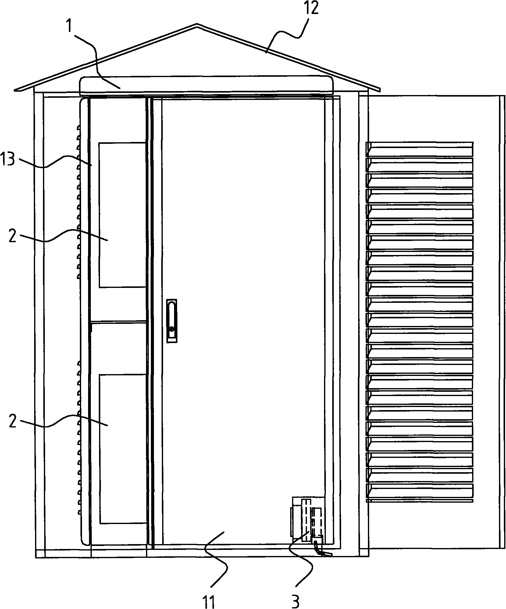
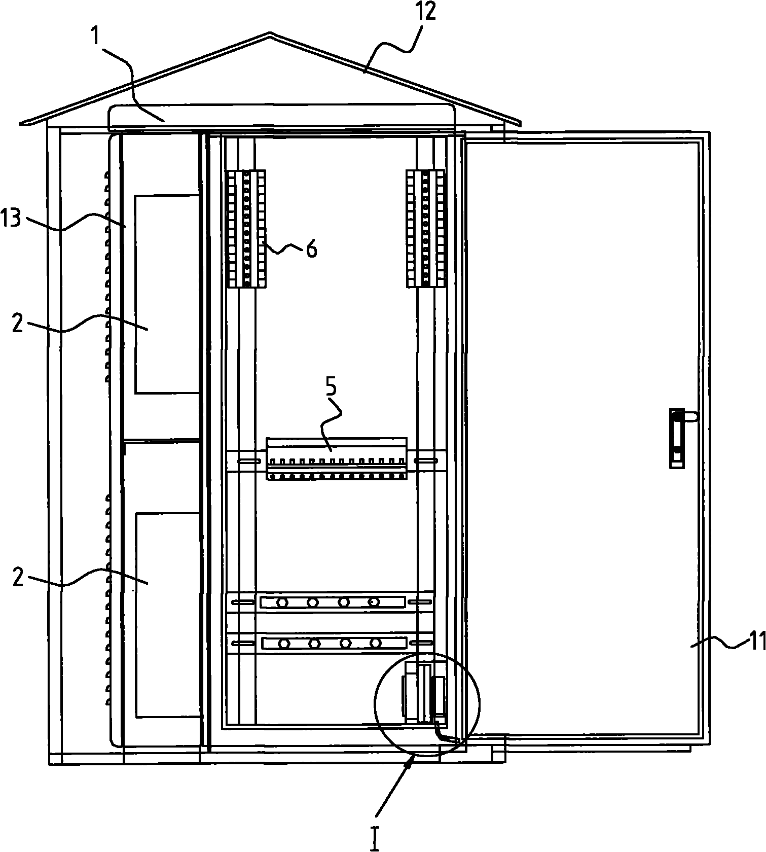
[0031] The terminal box of the present invention is mainly composed of a box body and a temperature and humidity control device for adjusting the temperature and humidity inside the box.

[0032] see Figure 2 to Figure 6 The box body is a relatively airtight structure composed of a box body body 1 and a box door 11 arranged on the front side of the box body body 1, and a terminal block 6 and an electrical component 5 are housed in the box body. Each wall of the box body 1 and the box door 11 are composed of an inner layer and an outer layer, and heat insulation cotton is filled between the inner layer and the outer layer, so that the temperature rise inside the box body can be reduced when exposed to the sun. Increase the heat insulation effect with the outside world when the temperature is adjusted. A wooden protective cover 12 is provided above the casing...


PUM


Abstract

The invention discloses a terminal box which comprises a box body and a temperature and humidity control device, wherein the box body is in an enclosed structure; the temperature and humidity control device comprises a controller, an air conditioner, a dehumidifier, a temperature sensor and a humidity sensor. The temperature sensor and the humidity sensor are respectively used for collecting temperature and humidity signals in the box body and transmitting the temperature and humidity signals to the controller. The controller is used for respectively comparing the temperature and the humidity in the box body with set operating temperature and set operating humidity. Moreover, when the temperature in the box body is higher than the maximum operating temperature or is lower than the minimum operating temperature, the controller switches on the air conditioner. When the humidity in the box body is higher than the maximum operating humidity, the controller switches on the dehumidifier. According to the invention, the temperature and the humidity in the box body are adjusted by using the air conditioner and the dehumidifier respectively and the operating requirements on precision electrical elements in the box body are better met by controlling the operation of the air conditioner and the dehumidifier through the controller.

Description

technical field [0001] The invention relates to a component of a substation, in particular to a terminal box of a substation. Background technique [0002] The terminal box is a kind of electrical equipment box commonly used in substations in the power industry. Traditional conventional terminal boxes were used in the past. The traditional conventional terminal box is just a simple metal shell, which can only provide the most basic physical protection for the electrical components in the box. The temperature and humidity conditions in the box are greatly affected by the external environment, so it can only meet the general electrical requirements. Component and Equipment Usage Requirements. Moreover, with the continuous development of the power industry, the development of smart grids and digital substations has been put on the agenda. The development of digital substations puts forward the requirement of decentralizing intelligent electronic equipment to the local area. T...

Claims


Application Information

Patent Timeline
Patent Type & Authority Applications(China)
IPC IPC(8): H02B1/14G05D22/02G05D23/19G08B21/10
Inventor 陈浩敏梁杰陈伟浩庄孟文
Owner GUANGZHOU ELECTRIC POWER DESIGN INST
Why Eureka
Try Eureka