
External water channel evaporative cooling horizontal motor

An evaporative cooling, horizontal motor technology, used in cooling/ventilation devices, electrical components, electromechanical devices, etc., can solve the problems of large temperature gradient of the stator core, difficult heat dissipation, uneven cooling, etc., to achieve obvious cooling effect, The effect of stable chemical properties and compact structure

Inactive Publication Date: 2007-01-03
INST OF ELECTRICAL ENG CHINESE ACAD OF SCI
View PDF0 Cites 17 Cited by
  • Summary
  • Abstract
  • Description
  • Claims
  • Application Information

AI Technical Summary

Problems solved by technology

[0007] The air-cooling method increases the ventilation system of the motor, and the wind friction loss is large, and the motor efficiency is low; the cooling is uneven, and the structural components such as the stator core and winding cannot be fully cooled, which reduces the power density and increases the volume of the motor; the noise is large, It cannot be applied in some occasions requiring low noise
[0008] ii In the external water cooling method, the main heat-generating parts of the motor stator are the stator winding and the stator core. The heat generated by the stator winding must first be transmitted to the stator core, and then the stator core will be transmitted to the cooling water through the stator casing, thus causing the stator core The temperature gradient is large, and the temperature distribution of the stator core is uneven; the end of the stator winding is completely exposed to the air and has no contact with the stator core, and the thermal conductivity of the air is much worse than that of the stator core, so this part of the heat is difficult to dissipate When the work is stopped, condensed water is easy to form at the end of the stator winding, which will damage the insulation of the end, thus affecting the life of the equipment

Method used


Image

  • External water channel evaporative cooling horizontal motor
  • External water channel evaporative cooling horizontal motor
  • External water channel evaporative cooling horizontal motor

Examples


Embodiment Construction

[0033] Further illustrate the present invention below in conjunction with accompanying drawing.

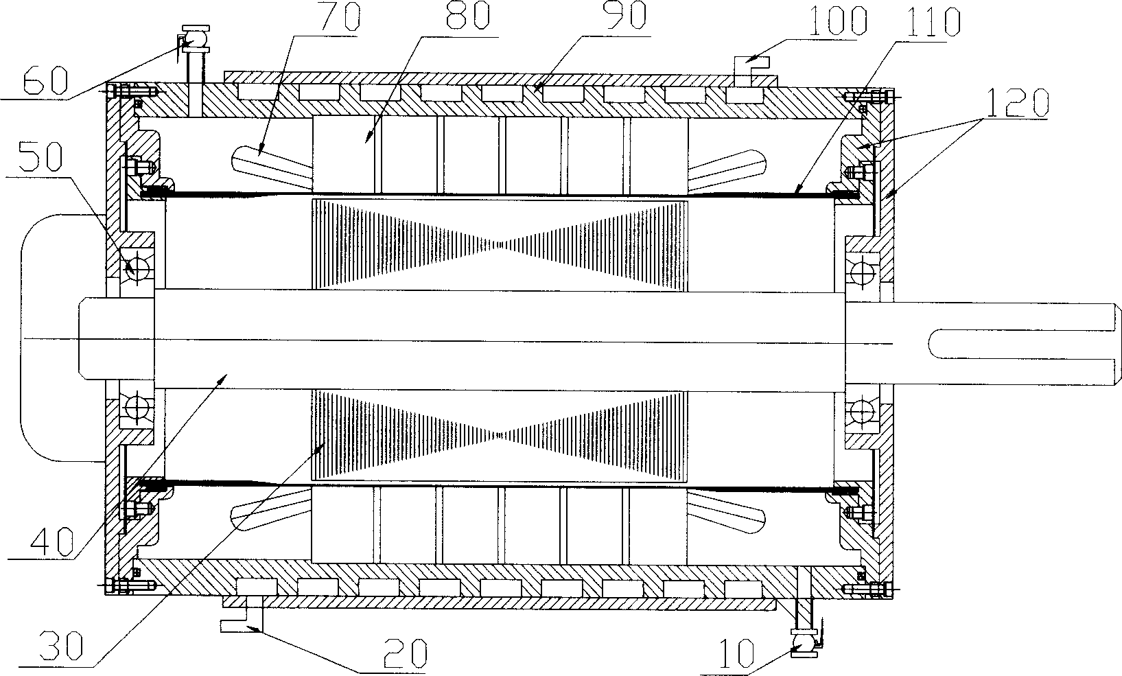
[0034] One of the specific embodiments of the present invention is as figure 1 as shown, figure 1 It is a schematic diagram of the structure of the outer channel type evaporative cooling motor. The outermost part in the figure is the motor casing, which includes the stator casing and the motor end cover 120 . The stator casing is mainly composed of an outer water channel 90, the outer water channel 90 is composed of an inner water jacket cylinder 903' and an outer water jacket cylinder 901', etc., the lower left end is provided with a water inlet 20, and the lower right end is provided with a cooling medium outlet 10, The left end of the upper part is provided with a cooling medium inlet 60, and the right end of the upper part is provided with a water outlet 100; a stator core 80 is installed in the middle of the stator casing, and the outer circle of the stator core 80 is an int...


PUM


Abstract

A outside watercourse evaporative cooling horizontal motor features adopting sealing between stator housing and front rear endplate, inner sleeve two ends and front rear endplate, constituting inclosed stator cavity to seal whole stator in stator cavity, evaporative cooling media implanting in stator cavity. Evaporative cooling media free-flow in stator cavity and can penetrate into stator core interior. Stator winding and stator core etc heating part generated heat quantity is conducted evaporative cooling media, when evaporative cooling media main unit temperature rises to corresponding pressure saturation temperature, media bubble and generate phase transition heat sink and vapour. Vapour is condensed and liquefied by flowing in water jacket cylinder inner wall in stator cavity upper part, then flowing back in stator cavity bottom evaporative cooling media, forming non - external power stator evaporative cooling self -circulation.

Description

technical field [0001] The invention relates to various small and medium-sized horizontal motors, in particular to an evaporative cooling horizontal motor. Background technique [0002] The motor is a kind of electromechanical energy conversion mechanism. In the process of electromechanical energy conversion, losses are inevitable, mainly including core loss, winding loss, mechanical loss, etc., and most of these losses eventually turn into heat, which makes the various parts of the motor The temperature rises. Therefore, the selection of cooling methods for small and medium-sized horizontal motors is an important part of motor design. [0003] Due to its small power, the cooling method of small and medium-sized horizontal motors is not as complicated as that of large generators, and air cooling is currently the dominant method. Its main structural form is blown from the outside of the fan, the axial ventilation surface is cooled, and the external fan installed on the rota...

Claims


Application Information

Patent Timeline
IPC IPC(8): H02K9/00H02K1/16H02K15/02
Inventor 王海峰傅德平顾国彪
Owner INST OF ELECTRICAL ENG CHINESE ACAD OF SCI
Learn More