
Method and circuit for dynamically equalizing battery management system

A battery management system and dynamic equalization technology, applied in battery circuit devices, electric vehicles, circuit devices, etc., can solve problems such as difficult large-scale implementation and application, resistance needs to dissipate heat, and large energy loss, etc., to achieve easy large-scale implementation and Application, the effect of reducing the number of components and circuit complexity of the charging and discharging device

Active Publication Date: 2014-02-26
SHENZHEN KELIE TECH
View PDF4 Cites 3 Cited by
  • Summary
  • Abstract
  • Description
  • Claims
  • Application Information

AI Technical Summary

Problems solved by technology

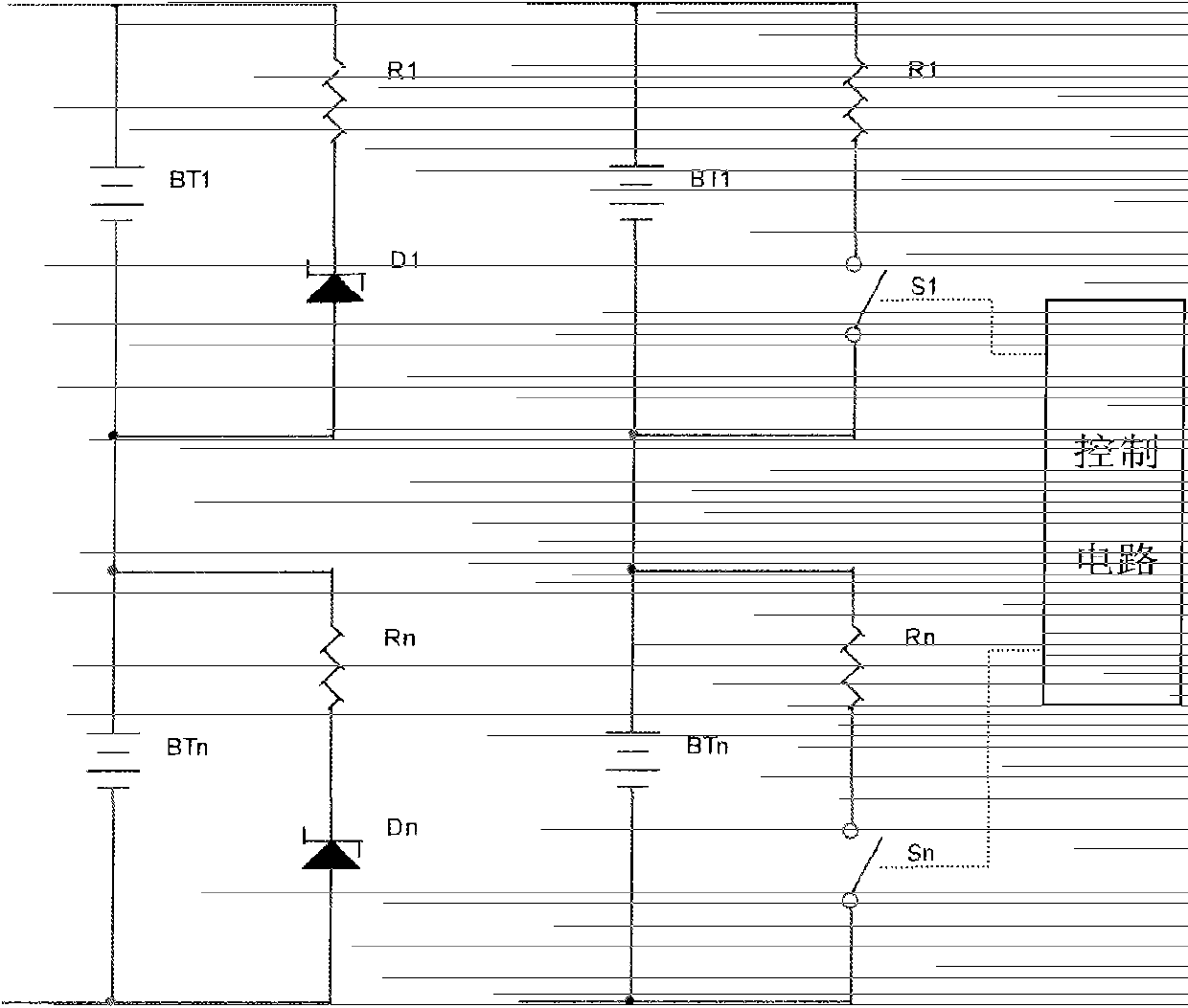
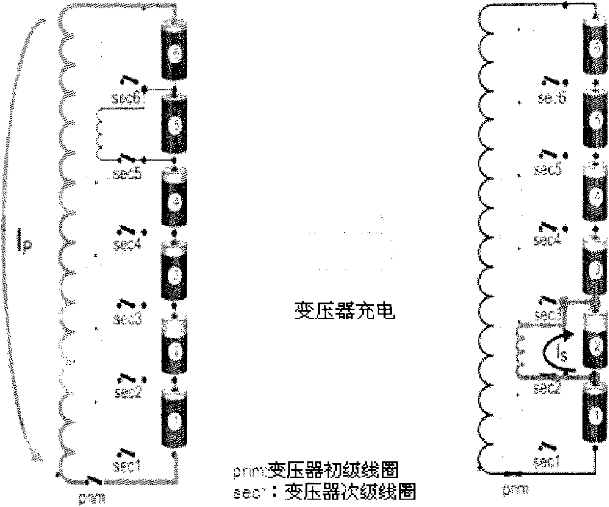
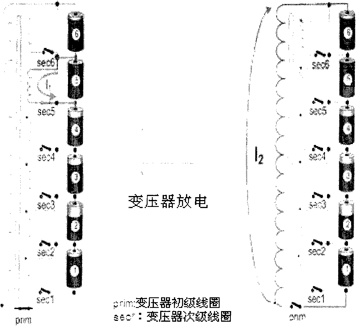
The most commonly used is to use such as figure 1 The energy balance circuit shown is simple and practical. Through the voltage regulator tubes D1, ... Dn or other control circuits of S1, ... Sn, which are switches respectively, when the voltage of a single battery BT1 or BTn is too high, it is automatically turned on. The bypass branch of a single battery BT1 or BTn provides a shunt to reduce the current flowing through the battery BT1 or BTn and avoid overvoltage of the battery BT1 or BTn. The disadvantage is that the energy loss is large, and the resistance needs to be dissipated. It can only be used for In low power circuits; such as figure 2 The energy-transfer balancing circuit shown can be used in large and medium power circuits. The low-voltage battery 2 can be charged separately through the conversion circuit, or the high-voltage battery 5 can be discharged separately through the conversion circuit, so that each single battery 1 ~6 The voltage is within the controllable range, and its defect is that it can only be used in a circuit with a small number of batteries connected in series. Otherwise, the conversion circuit uses too many bidirectional switches and its control circuit, the cost is too high, and the transformer taps of the conversion circuit are too many , it is difficult to implement and apply on a large scale

Method used


Image

  • Method and circuit for dynamically equalizing battery management system
  • Method and circuit for dynamically equalizing battery management system
  • Method and circuit for dynamically equalizing battery management system

Examples


specific Embodiment approach 1

[0052] a kind of like Figure 4 , 5 The dynamic equalization circuit of the battery management system shown in the figure includes M (>1) bidirectional isolation converters Sub1~SubM for energy transfer, and the forward input terminals of the bidirectional isolation converters Sub1~SubM are connected to the main buses Bus+ and Bus -connection, convert the energy of the busbars Bus+, Bus- into positive and negative voltage output, and manage the corresponding M groups of sequentially connected battery packs, and each sequentially connected battery pack consists of N (>1) single-cell batteries BT1, ... BTn are sequentially connected in series. The bi-directional isolation converters Sub1-SubM are bi-directional isolation converters, and the bi-directional isolation converters Sub1-SubM are DC conversion power sources that can work in both forward and reverse directions. The positive and negative voltage outputs of the bidirectional isolation converters Sub1-SubM are two isolat...

specific Embodiment approach 2

[0061] a kind of like Figure 4 , 6 The circuit composition of the dynamic equalization circuit of the battery management system shown is basically the same as that of the first embodiment. The difference is that the positive and negative voltage outputs of the bidirectional isolation converter Sub1~SubM are one positive and negative voltage output, and the rear stage of the bidirectional isolation converter is equipped with four polarity selection switches (S1c1, S1c2, S1c3 and S1c4), …… (SMc1, SMc2, SMc3 and SMc4) composed of a bridge polarity selection switch group, the two ends of a pair of corners of the bridge polarity selection switch group are respectively connected to the positive and negative voltage output terminals of the bidirectional isolation converter Sub1~SubM connection, and the opposite ends are respectively connected to one of the two pairs of 1# collection busbars to n# collection busbars, which are used to realize the polarity transformation of the colle...


PUM


Abstract

The invention relates to a method and a circuit for dynamically equalizing a battery management system. The method comprises the following steps of: 1) detecting the voltage of each single battery in each group of battery packs sequentially connected in series by using embedded control software; 2) judging the location number of the single battery which needs to be charged or discharged separately and has excessively low or high voltage by using a central processing unit (CPU); 3) giving a control command out by using the CPU, controllably gating a corresponding polarity selecting switch block to perform polarity inversion on a collection bus, controllably gating a corresponding battery selecting switch block to perform polarity matching at the same time, controlling the working direction of a bidirectional isolation transformer and connecting the single battery which needs to be charged or discharged separately and has the excessively low or high voltage to the connection bus for charging or discharging so as to realize energy transfer; and 4) repeating the steps 1) to 3) until the voltage of each single battery in each group of battery packs sequentially connected in series is in a set allowable error range so as to realize dynamic equilibrium. The number of charging and discharging devices and circuit complexity of the battery management system can be reduced remarkably.

Description

technical field [0001] The invention relates to a battery management system, in particular to a dynamic equalization method and a dynamic equalization circuit for the battery management system. Background technique [0002] There are many solutions for the existing iron-lithium battery management system. The most commonly used is the use of figure 1 The energy balance circuit shown is simple and practical. Through the voltage regulator tubes D1, ... Dn or other control circuits of S1, ... Sn, which are switches respectively, when the voltage of a single battery BT1 or BTn is too high, it is automatically turned on. The bypass branch of a single battery BT1 or BTn provides a shunt to reduce the current flowing through the battery BT1 or BTn and avoid overvoltage of the battery BT1 or BTn. The disadvantage is that the energy loss is large, and the resistance needs to be dissipated. It can only be used for In low power circuits; such as figure 2 The energy-transfer balancin...

Claims


Application Information

Patent Timeline
Patent Type & Authority Patents(China)
IPC IPC(8): H02J7/02H02J7/00
Inventor 张泱渊仝瑞军
Owner SHENZHEN KELIE TECH
Learn More