Lead bending die of rotor winding and processing method

A rotor coil and processing method technology, applied in the field of hydroelectric generators, can solve the problems of high processing and manufacturing precision and mold manufacturing costs, increased man-hours and energy consumption, long debugging time, etc., and achieve high bending quality of coil leads and structural Simple, low-cost-to-produce effect

Inactive Publication Date: 2010-12-15
TIANJIN TIRNFR HEAVY HYDROELECTRIC FRCILITY CO LTD
View PDF4 Cites 2 Cited by
  • Summary
  • Abstract
  • Description
  • Claims
  • Application Information

AI Technical Summary

Problems solved by technology

[0002] At present, in the existing technology, the production of medium and large-scale rotor coil lead wire bending production adopts the bending die to be installed on the hydraulic press to carry out the bending production of the upper and lower leads at th

Method used


Image

  • Lead bending die of rotor winding and processing method
  • Lead bending die of rotor winding and processing method
  • Lead bending die of rotor winding and processing method

Examples


Embodiment 1

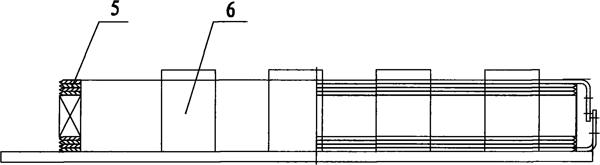
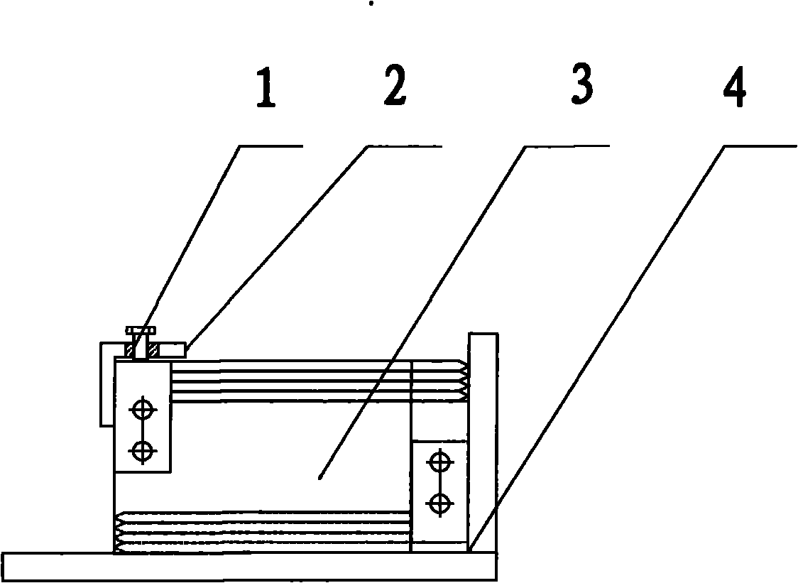
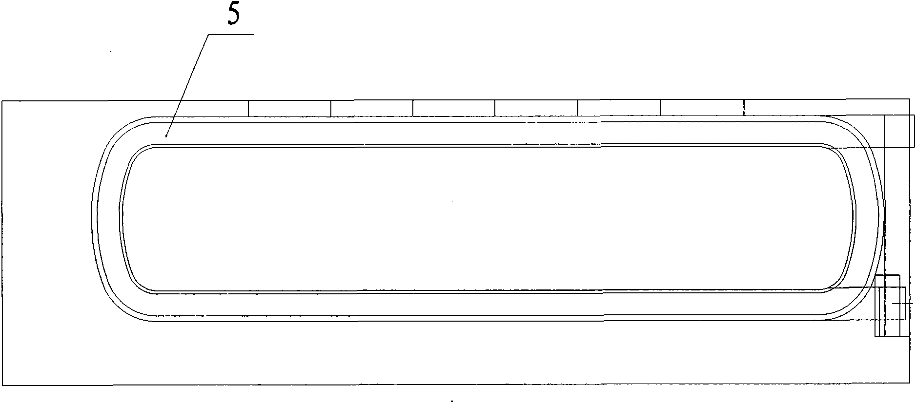
[0029] A rotor coil lead wire bending die, including a base plate 4, a wire pressing plate 2, a positioning plate 3, a support plate 6, a compression bolt 1, etc., the base plate and the support plate are vertically welded together so that the length direction of the rotor coil 5 is close to each other Accurate positioning on the support plate. The width dimension of the positioning plate is processed according to the length of the lead wire in the design drawing, and a notch is opened at the bending position of the right lead wire at the bottom. The position size is designed on the positioning plate, and the side plate is connected with the positioning plate, and then the positioning plate is placed on the bottom plate and welded firmly. Weld the crimping plate to the left side of the positioning plate. On the bending tooling, the positioning plate is used for positioning and bending the ends of the rotor coils to ensure consistent bending positions of the lead wires. A cla...

Embodiment 2

[0031] A rotor coil lead wire bending processing method, using the bending die in Embodiment 1 for processing, the rotor coil lead wire bending processing process includes annealing of the rotor coil through copper bars, flat winding, secondary annealing of the rotor coil, cold pressing, After the lead wire is marked, tinned and drilled, the rotor coil lead wire is bent. The lead wire bending process is to place the rotor coil on the bending die, and position the end of the rotor coil against the positioning plate. The lead wires of the copper bars are clamped by the compression bolts through the crimping plate, and the operator uses an iron hammer to beat the lead wires according to the shape, and the lead wires are simmered and bent.

[0032] Concrete operation process of the present invention:

[0033] 1. First process and assemble according to the design drawing of the rotor coil bending tooling. 2. Mark the lead wire, level the lead wire, mark the lead wire, enamel tin a...


PUM


Abstract

The invention relates to a lead bending die of a rotor winding and a processing method, belonging to the technical field of hydraulic generators. The lead bending die of a rotor winding is provided with a soleplate, a line-pressing plate, a positioning plate and a supporting plate, wherein the soleplate and the supporting plate are vertically fixed together, the positioning plate is fixed on the soleplate and provided with a notch in a position where a lead is pressed to be bent at the bottom, and the line-pressing plate is fixed on the positioning plate which is used for positioning and bending the end of the rotor winding. The lead bending processing method of the rotor winding comprises the following steps of: annealing the rotor winding through a copper bar, edgewise winding, secondarily annealing, cold pressing, scribing the lead, dipping tin and drilling holes and carrying out the lead bending treatment of the rotor winding; and putting the rotor winding on a bending die, firmly clamping the copper bar lead by a compressing bolt through the line-pressing plate and bending the lead by adopting shape-beating mode of an iron hammer. The invention has the advantages of simple structure, rapid operation, time and labor saving, less working hour consumption, high production efficiency, high winding lead bending quality, and the like.

Description

technical field [0001] The invention belongs to the technical field of hydraulic generators, and in particular relates to a rotor coil lead wire bending die and a processing method. Background technique [0002] At present, in the existing technology, the production of medium and large-scale rotor coil lead wire bending production adopts the bending die to be installed on the hydraulic press to carry out the bending production of the upper and lower leads at the same time, and the required manufacturing accuracy and mold manufacturing cost of the upper and lower modules of the bending die High, long debugging time during mold installation, time-consuming and labor-intensive, increased working hours and energy consumption. Contents of the invention [0003] The invention provides a rotor coil lead wire bending die and a processing method in order to solve the technical problems existing in the known technology. [0004] In order to reduce the production cost of the motor, ...

Claims


Application Information

Patent Timeline
IPC IPC(8): H02K15/04
Inventor 路春玲单庆臣
Owner TIANJIN TIRNFR HEAVY HYDROELECTRIC FRCILITY CO LTD
Why Eureka
Try Eureka