Method and apparatus for obtaining cavities on surfaces of ceramic items

A technology for ceramics and products, used in ceramic molding machines, metal processing equipment, grinding/polishing equipment, etc., which can solve problems such as long time, inaccuracy, and rapid wear of milling cutters

Inactive Publication Date: 2010-05-19
SITI B&T GRP
View PDF4 Cites 2 Cited by
  • Summary
  • Abstract
  • Description
  • Claims
  • Application Information

AI Technical Summary

Problems solved by technology

[0010] The first disadvantage is that due to the mechanical resistance of tiles or slabs already baked, milling by hand is rather time consuming, cumbersome and difficult to process
[0011] Due to the large number of grooves (on average 4 must be formed in each tile and slab), this method of forming grooves results in a significant increase in the cost of manufacture of ventilation walls ...

Method used


Image

  • Method and apparatus for obtaining cavities on surfaces of ceramic items
  • Method and apparatus for obtaining cavities on surfaces of ceramic items

Examples


Embodiment Construction

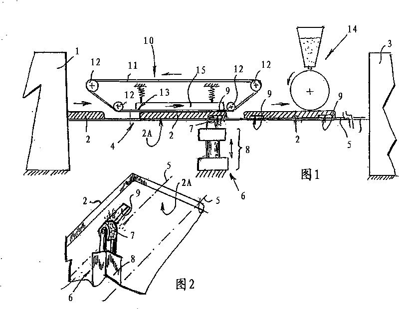
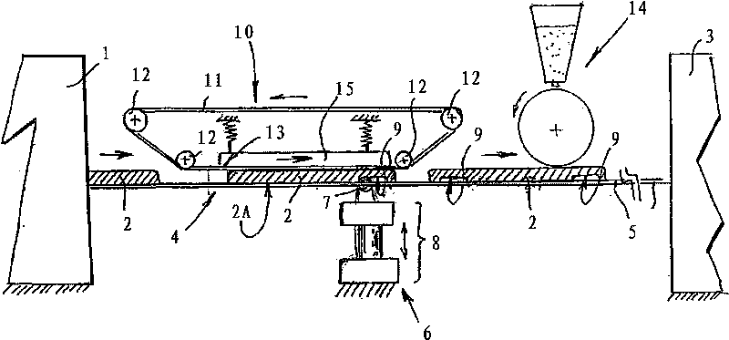
[0024] According to the drawings, numeral 1 denotes a drying device for ceramic products such as tiles 2 , and numeral 3 denotes a kiln for firing tiles 2 .

[0025] A conveyor line 4 , usually with parallel belts 5 , is arranged between the drying unit 1 and the kiln 3 , while the tiles 2 located thereon are transported from the drying unit to the kiln 3 for firing for final stabilization.

[0026] The conveying line 4 comprises a removal device 6 mounted below the parallel belt 5 and having a grinding wheel 7 mounted on a lifting or lowering unit generally indicated by the numeral 8, between a working position and a stop position for removing ceramic material between movement.

[0027] An enamel covering device or decoration device can also be installed between the drying device 1 and the kiln 3 , downstream of the removal device 6 , which is schematically indicated by numeral 14 .

[0028] The wheels 6A of the removal device 6, or other components known to those skilled in...


PUM


Abstract

The method for obtaining cavities (9) in surfaces (2A) of ceramic items (2), according to predetermined directions and patterns, involves the creation of cavities (9) in said surfaces (2A) of said ceramic items (2) in a high-cohesion green state.

Description

technical field [0001] The present invention relates to a method for obtaining grooves on the surface of a ceramic product and a device for manufacturing a ceramic product having at least one grooved surface, especially suitable for forming desired shapes and dimensions on ceramic products such as tiles, slabs, etc. groove. Background technique [0002] In one particular class of applications, the laying surface of ceramic products, such as tiles, slabs, etc., requires grooves formed in a particular pattern and arrangement. [0003] This requirement arises, for example, when tiles or slabs are used to form ventilated walls, ie walls covering building facades, which are maintained at predetermined distances in order to allow airflow to circulate in the interstices defined therebetween. [0004] These ventilated walls are mainly used for two purposes: the first is to create a surface that acts as a thermal barrier to protect the building from changes in outside temperature so...

Claims


Application Information

Patent Timeline
IPC IPC(8): B28B11/08B28B11/10B24B19/02
CPCB28B11/243B28B3/20B28B11/12B28B3/021
Inventor F·塔罗齐
Owner SITI B&T GRP
Why Eureka
Try Eureka