

Active clamp synchronous rectification forward converter
A forward converter and synchronous rectification technology, applied in the field of electronics, can solve problems such as loss efficiency and decrease, and achieve the effect of improving efficiency
Inactive Publication Date: 2010-12-15
UNIV OF ELECTRONIC SCI & TECH OF CHINA
View PDF5 Cites 40 Cited by
- Summary
- Abstract
- Description
- Claims
- Application Information
AI Technical Summary
Problems solved by technology
[0006] In order to solve the loss caused by the drive voltage of the rectifier tube and the freewheeling tube being too high or too low in the synchronous rectification circuit of the existing active clamp synchronous rectification forward converter and the common conduction phenomenon of the rectifier tube and the freewheeling tube The problem caused by the drop in efficiency, the present invention provides an active clamp synchronous rectification forward converter
Method used
View moreImage
Smart ImageViewing Examples

Examples
Embodiment Construction
[0022] The technical solution of the present invention has been fully and completely described in the content of the invention, and will not be repeated here.
Login to View More PUM
 Abstract
The invention discloses an active clamp synchronous rectification forward converter, and belongs to the technical field of electronics. The converter comprises a direct current input power supply, an input capacitor, a main transformer T1, a synchronous rectifier circuit, a filter circuit, a voltage sampling circuit, an optical coupling feedback circuit, a PWM control circuit and an active clamp circuit; the synchronous rectifier circuit consists of a rectifier tube and a driving circuit thereof, and a freewheeling tube and a driving circuit thereof, wherein the driving voltage of the rectifying tube is generated by a secondary auxiliary winding of the main transformer, and has the same phase as that of a first switching tube of the active clamp circuit; and the driving voltage of the freewheeling tube is generated by coupling the driving voltage of a second switching tube in the active clamp circuit, so the driving voltage has the same phase as that of the second switching tube in the active clamp circuit. The synchronous rectifier circuit of the forward converter adopted the fixed driving voltage, has the dead zone time same as the active clamp circuit, and can improve the conversion efficiency and reduce the loss of the active clamp synchronous rectification forward converter.
Description
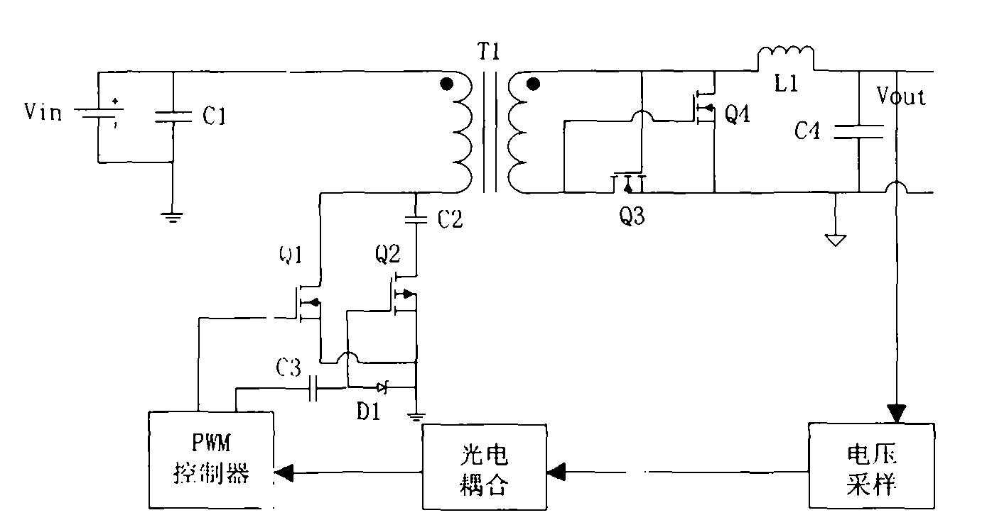
technical field [0001] The invention belongs to the field of electronic technology, and relates to a DC / DC converter of active clamp synchronous rectification, especially a forward converter whose secondary adopts self-driven synchronous rectification. Background technique [0002] At present, an active clamp synchronous rectification forward converter usually includes a DC input power supply, an input capacitor, a main transformer T1, a synchronous rectification circuit, a filter circuit, a voltage sampling circuit, an optocoupler feedback circuit, a PWM control circuit and an active clamping circuit composition. Its circuit structure is as figure 1 Shown: the DC input power supply Vin charges the input capacitor C1, and the discharge current of the input capacitor C1 is input to the primary terminal of the main transformer T1 with the same name; the primary terminal of the main transformer T1 with the same name is grounded through an active clamping circuit. The active c...
Claims
Login to View More Application Information
Patent Timeline
 IPC IPC(8): H02M3/335
CPCY02B70/1475Y02B70/10
Inventor张怀武陈鉴宇龚军勇杨青慧钟智勇王兴蔚
OwnerUNIV OF ELECTRONIC SCI & TECH OF CHINA