
a driving circuit

A driving circuit and driving voltage technology, applied in the direction of electrical components, output power conversion devices, etc., can solve the problem of large physical layout of the driving circuit

Active Publication Date: 2021-07-06
HEFEI GEYI INTEGRATED CIRCUIT CO LTD +1
View PDF7 Cites 0 Cited by
  • Summary
  • Abstract
  • Description
  • Claims
  • Application Information

AI Technical Summary

Problems solved by technology

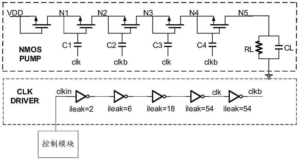
[0005] The driving circuit provided by the present invention solves the problem that when the existing driving circuit drives many stages of charge pumps, many inverters need to be connected in parallel, which makes the physical layout of the driving circuit very large.

Method used


Image

  • a driving circuit
  • a driving circuit
  • a driving circuit

Examples


Embodiment Construction

[0074] The following will clearly and completely describe the technical solutions in the embodiments of the present invention with reference to the accompanying drawings in the embodiments of the present invention. Obviously, the described embodiments are some of the embodiments of the present invention, but not all of them. Based on the embodiments of the present invention, all other embodiments obtained by persons of ordinary skill in the art without creative efforts fall within the protection scope of the present invention.

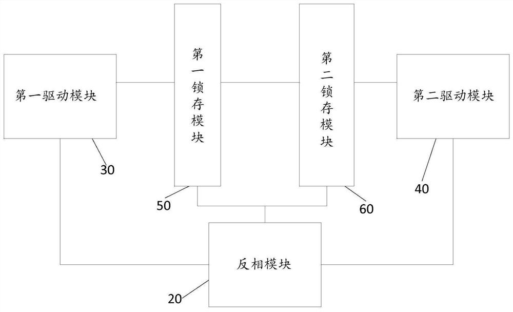
[0075] refer to figure 2 , which shows a schematic diagram of the module of the driving circuit, which may specifically include:

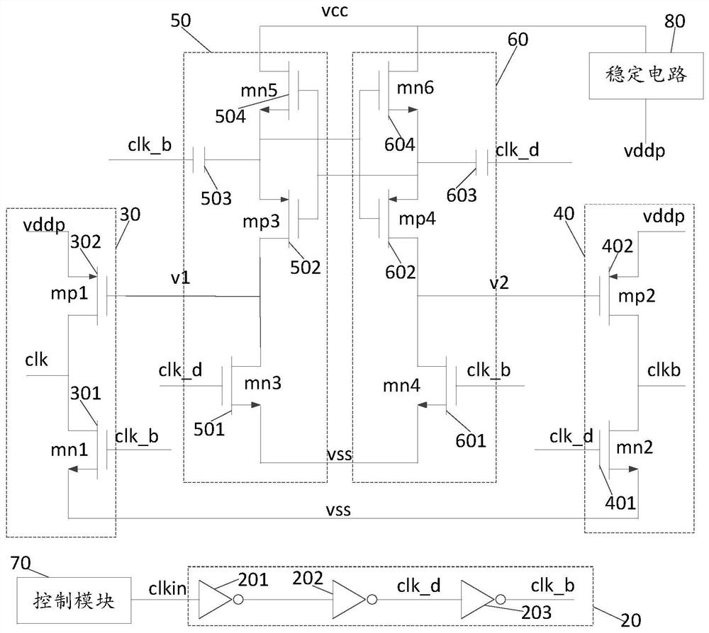
[0076] The inverter module 20 , the first driving module 30 , the second driving module 40 , the first latch module 50 and the second latch module 60 .

[0077] The inverting module 20 is respectively connected to the first driving module 30, the second driving module 40, the first latch module 50 and the second latch mod...


PUM


Abstract

The invention provides a driving circuit. The driving circuit is applied to a non-volatile memory, and the non-volatile memory includes: a charge pump circuit and a voltage stabilizing circuit, the driving circuit is used to provide a driving voltage for the charge pump circuit, and the driving voltage includes a first driving voltage and a second driving voltage, the driving circuit includes: an inverting module, a first driving module, a second driving module, a first latch module and a second latching module, the inverting module and the first The driving module, the second driving module, the first latch module and the second latch module are respectively connected, and the first driving module is connected to the first latch module and the inverting module respectively , the second drive module is connected to the second latch module and the inversion module respectively, the first latch module is connected to the first drive module and the inversion module respectively, and the second latch module It is respectively connected with the second driving module and the inverting module.

Description

technical field [0001] The invention relates to the field of nonvolatile memory, in particular to a driving circuit. Background technique [0002] At present, the non-volatile memory is basically provided by the charge pump to meet the operating voltage for the non-volatile memory. The charge pump is a switched capacitor voltage converter, which uses the so-called "fast" or "pumping" capacitor, and A DC converter with non-inductance or transformer for energy storage can increase or decrease the input power supply voltage, and can also be used to generate negative voltage. Its internal MOS switch array controls the charging and discharging of the flying capacitor in a certain way, so that The input voltage is multiplied or reduced by a certain factor (1 / 2, 2 or 3) to obtain the required output voltage. A general charge pump circuit includes a main structure and a drive circuit, where the main structure is the main source of the output voltage of the charge pump circuit. Comp...

Claims


Application Information

Patent Timeline
Patent Type & Authority Patents(China)
IPC IPC(8): H02M1/08
CPCH02M1/08
Inventor 黄鹏邓龙利
Owner HEFEI GEYI INTEGRATED CIRCUIT CO LTD
Learn More