Network topology identification method based on flow analysis

A network topology and traffic analysis technology, applied in the field of large-scale IP network topology detection, can solve the problems of increased node burden, limited application and long detection cycle, etc., to achieve the effect of increased node burden

Inactive Publication Date: 2010-12-15
UNIV OF ELECTRONICS SCI & TECH OF CHINA
View PDF3 Cites 17 Cited by
  • Summary
  • Abstract
  • Description
  • Claims
  • Application Information

AI Technical Summary

Problems solved by technology

[0010] In order to solve the above-mentioned technical problems, the present invention proposes a network topology inference method based on traffic analysis. The present invention's inference of topology depends entirely on the existing network traffic, and does not require any form of active detection and additional IP packet t...

Method used


Image

  • Network topology identification method based on flow analysis
  • Network topology identification method based on flow analysis
  • Network topology identification method based on flow analysis

Examples


Embodiment 1

[0041] A method for inferring network topology based on traffic analysis, characterized in that the steps include:

[0042] a. Deploy a measurement point on the network backbone link to capture and analyze all IP packets flowing through the link. The capture refers to: using common tools such as libpcap and general network packet capture technology, at the measurement point Receive the IP grouping that transmits in the network on the network card, described analysis refers to: observe TCP session, obtain the path characteristic of each IP host of both sides of each TCP conversation to described measuring point respectively, and described path characteristic comprises route hop count (hop_count ) and round-trip time delay (RTT), set a fixed time period T, and obtain an analysis result value of each path characteristic within a time period;

[0043] b. Through continuous capture and analysis of multiple time periods, the time series of the path characteristics of each IP host to...

Embodiment 2

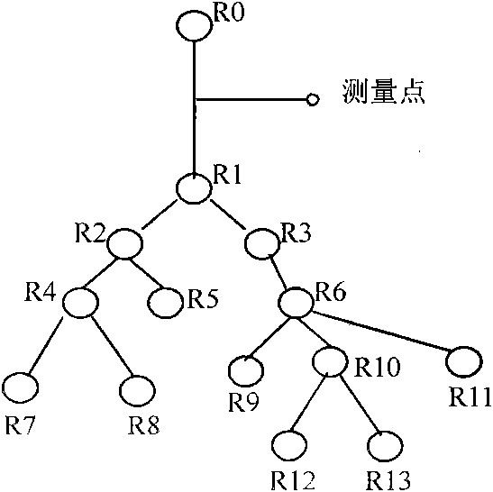
[0053] (1) Deploy measurement points on the network backbone link to capture and analyze all IP packets flowing through the link. Such as figure 1 shown.

[0054] (2) Analyze all IP packets to obtain measurement results. By observing the TCP session, the characteristics of the paths from the hosts on both sides of each TCP session to the measurement point are found. These characteristics include 2: routing hop count (hop-count), round-trip time delay (RTT).

[0055] The method of obtaining the routing hop count is relatively common. Analyze the TTL field value of each IP packet, and subtract the TTL value from 255 to get the hop-count value from the source host to the measurement point of the IP packet, namely: hop_count=255-TTL. This method is widely used and is not described in detail in the specification.

[0056] There are also many methods for obtaining RTT. Currently, commonly used analysis methods include SA method, SS method, Karn method, and Running method. These...

Embodiment 3

[0078] The principle of the present invention is: select a certain backbone link in the network backbone, and deploy measurement points (Measurement Points) to analyze the traffic. Suppose any two different nodes in the network (H i and H j ) to the measurement point, there are respective paths (P i and P j ), define P i and P j The correlation is R, then R largely reflects P i and P j degree of overlap. The research shows that the more shared links of nodes in the network, the more similar the characteristics of the nodes, and the greater the correlation of the change trend of their performance indicators (time series obtained through measurement). For example, when path congestion intensifies, the performance of different nodes in the path will show a similar trend of change (delay and packet loss rate increase, available bandwidth decreases). Therefore, deploying measurement points in the network backbone link, for node H i and H j Measure the performance indicato...


PUM


Abstract

The invention discloses a network topology identification method based on flow analysis, relating to the technical field of large-scale IP network topology probe. The method comprises the following steps: deploying measuring points on the backbone link of the network, analyzing the flow hop-count and the round-trip-time (RTT) and then carrying out primary clustering and secondary clustering, thus forming the network topology. The method solves the following technical problems in the prior art: a large amount of detection flow is generated, the burden of the nodes is increased, application is limited and the detection cycle is long. The identification result of the method is more accurate.

Description

technical field [0001] The invention relates to the technical field of large-scale IP network topology detection. Background technique [0002] The topology detection of large-scale IP networks has once become a hot spot in the field of network management. Various research institutions have launched different research projects to realize the discovery of the Internet structure. Most of these researches are based on active detection technology represented by traceroute. However, such methods have become more and more obvious to show their inherent flaws: [0003] (1) The overhead is huge. Due to the huge size of the Internet, the measurement point must send a large number of detection packets to a large number of target nodes, resulting in a large amount of detection traffic, which increases the burden on the nodes and makes the network management problem more complicated. [0004] (2) The application is limited. The detection method of the active mode depends on the respo...

Claims


Application Information

Patent Timeline
IPC IPC(8): H04L12/26H04L12/56H04L12/24
Inventor 黄鹂声汪文勇
Owner UNIV OF ELECTRONICS SCI & TECH OF CHINA
Why Eureka
Try Eureka