
Electronic equipment housing with electromagnetic-shielding efficient heat radiating hole based on frequency selecting surface technique

A frequency selective surface, electromagnetic shielding technology, applied in the direction of electrical equipment shell/cabinet/drawer, magnetic field/electric field shielding, electrical components, etc., can solve the problem of inability to shield electromagnetic heat dissipation performance, poor performance, and achieve obvious electromagnetic shielding effect , The effect of stable shape performance and large area

Inactive Publication Date: 2010-12-15
HARBIN INST OF TECH
View PDF3 Cites 3 Cited by
  • Summary
  • Abstract
  • Description
  • Claims
  • Application Information

AI Technical Summary

Problems solved by technology

[0003] In order to solve the problem of not being able to shield electromagnetic waves and poor heat dissipation performance in the case of better shielding while meeting the requirements of heat dissipation, the present invention proposes an electronic device with electromagnetic shielding efficiency cooling holes based on frequency selective surface technology. Equipment housing

Method used


Image

  • Electronic equipment housing with electromagnetic-shielding efficient heat radiating hole based on frequency selecting surface technique
  • Electronic equipment housing with electromagnetic-shielding efficient heat radiating hole based on frequency selecting surface technique
  • Electronic equipment housing with electromagnetic-shielding efficient heat radiating hole based on frequency selecting surface technique

Examples


specific Embodiment approach 1

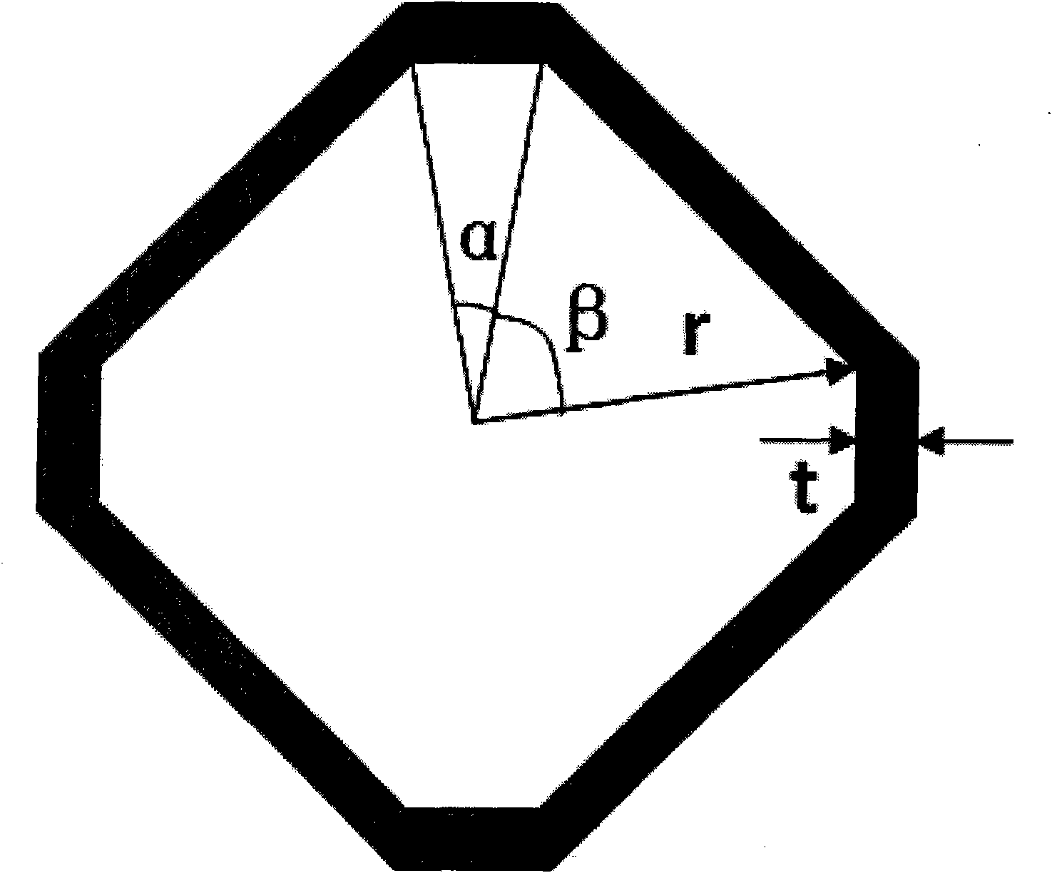
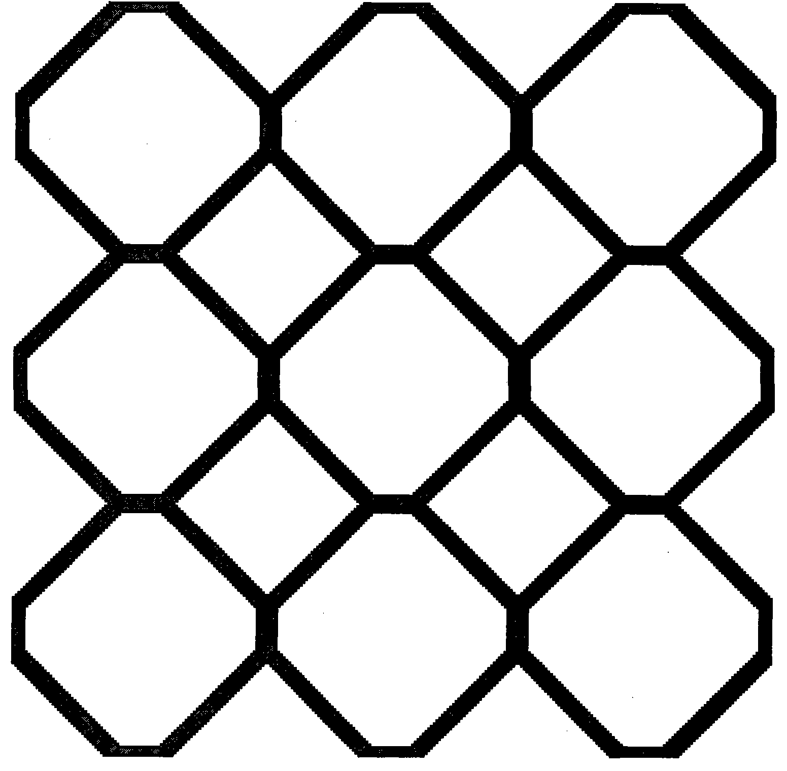
[0012] Specific implementation mode one: combine figure 1 with figure 2 Describe this embodiment mode, this embodiment mode is that the heat dissipation area of ​​its electronic equipment outer casing is provided with the heat dissipation hole that is composed of at least nine octagonal heat dissipation hole units arranged in a periodic manner; each octagonal heat dissipation hole unit is composed of four The side corresponding to the central angle α and the four sides corresponding to the central angle β are sequentially connected at intervals to form a centerline symmetrical octagon; two adjacent octagonal cooling hole units correspond to the two central angles α The sides of each of the four adjacent octagonal cooling hole units are overlapped to form a shared side, and the sides corresponding to the four central angles of each of the four adjacent octagonal cooling hole units are β to form a square, which satisfies 0°<α≤20°, α+β=90° . The material of the octagonal cooli...

specific Embodiment approach 2

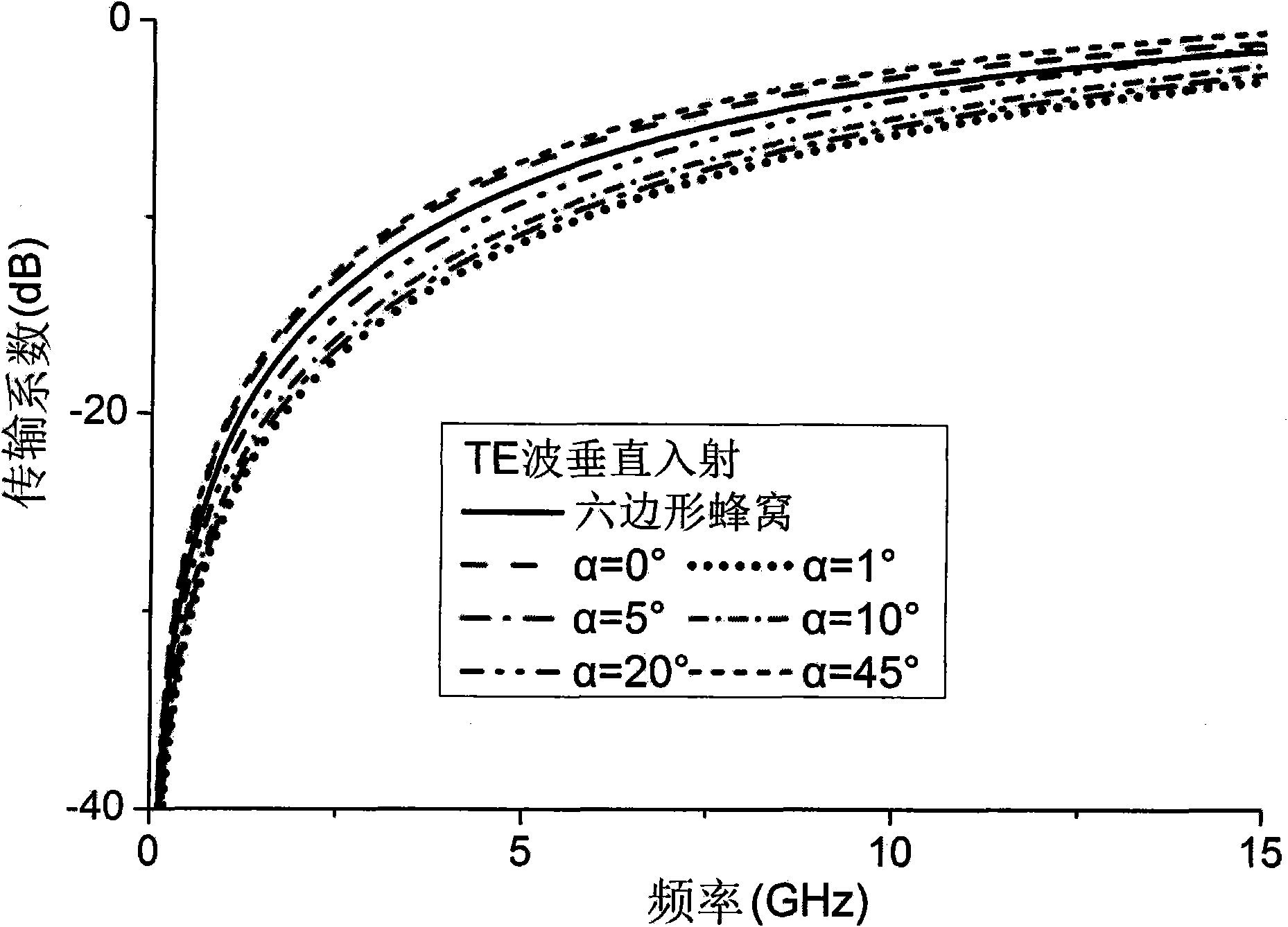
[0013] Specific implementation mode two: combination Figure 1 to Figure 7 Describe this embodiment, the difference between this embodiment and specific embodiment 1 is that the parameters of the octagonal cooling hole unit in this embodiment are as follows: (length unit: mm)

[0014]

[0015]

[0016] Other compositions and connection methods are the same as those in Embodiment 1. Based on the FSS technology, it can be known that for the porous frequency selective surface, the hole with the longest perimeter in the hollow area will directly affect the frequency selective characteristics of the structure. By increasing the length of the diagonal gap, the shielding effectiveness of the structure can be improved. Based on this, if the central angle α between the shared sides of the octagonal cooling hole units is different, the electromagnetic shielding effect should be different. Therefore, under the condition that the width of the metal strip and the duty cycle are kept...


PUM


Abstract

The invention relates to a heat radiating hole on electronic equipment, in particular to an electronic equipment housing with an electromagnetic-shielding efficient heat radiating hole based on a frequency selecting surface technique, solving the problems of no electromagnetic shielding when meeting the requirement of heat radiation and poor heat radiation under the condition of better shielding. A heat radiating hole formed by periodically arranging at least nine octagonal heat radiating hole units is arranged in a heat radiating zone of the electronic equipment housing; each octagonal heat radiating hole unit is an symmetrical-center line octagon formed by sequentially connecting sides which correspond to four central angles alpha with sides which correspond to four central angles beta at intervals; and the sides which correspond to the two central angles alpha of two neighboring octagonal heat radiating hole units are coincided into a whole to form a shared side, the sides which correspond to the four central angles beta of the four neighboring octagonal heat radiating hole units form a square, wherein the alpha is greater than 0 degree and not greater than 20 degrees, and the sum of the alpha and the beta is equal to 90 degrees. The heat radiating hole has the advantages of simple shape and structure, easy processing and low cost and is applied to the electronic equipment housing.

Description

technical field [0001] The invention relates to a cooling hole on an electronic device, in particular to a cooling hole with electromagnetic shielding effect. Background technique [0002] Most of the existing electronic devices will release a large amount of heat from their internal electronic components when they are working. These electronic components will reduce their service life in an overheated environment for a long time. Therefore, it is necessary to release the heat inside the machine box in time. Existing machine casings adopt the method of setting many heat dissipation holes on the box body to dissipate heat. For the design of heat dissipation holes, on the one hand, it is necessary to take into account the different radiation frequencies of different electronic devices, and the same electronic device may also radiate more radiation at the same time. Therefore, the designed cooling holes should provide greater impedance in the largest possible frequency range. ...

Claims


Application Information

Patent Timeline
Patent Type & Authority Applications(China)
IPC IPC(8): H05K5/00H05K7/20H05K9/00
Inventor 吴群张少卿李宛露张桐王晓鲁高前超
Owner HARBIN INST OF TECH
Learn More