Inner rotor brushless motor and manufacturing method thereof

An inner rotor and motor technology, applied in the field of inner rotor brushless motors, can solve problems such as loss of magnetic flux, reduction of mechanical strength of the iron core, deformation of the shape of the iron core, etc., and achieve the effect of increasing the degree of freedom

Inactive Publication Date: 2009-04-22
MABUCHI MOTOR
View PDF1 Cites 15 Cited by
  • Summary
  • Abstract
  • Description
  • Claims
  • Application Information

AI Technical Summary

Problems solved by technology

Therefore, if Figure 8 As shown in (A) or (C), part of the laminated iron core needs to cut off the bridge part to make a non-bridge part, but if the ratio of the non-bridge part is increased, the mechanical strength of the core will decrease
As a result, the winding tension will be directly applied to the iron core when the winding machine is winding, which will cause deformation of the iron core shape and decrease the roundness of the iron core.
On the contrary, if the roundness of the iron core is to be maintained, the ratio of the non-bridging portion cannot be increased, and the generated magnetic flux will be lost
Moreover, the moving space of the nozzle end of the winding machine needs to be in the slot, therefore, all the space in the slot cannot be occupied by the winding, and the guarantee of the winding space factor is restricted.

Method used


Image

  • Inner rotor brushless motor and manufacturing method thereof
  • Inner rotor brushless motor and manufacturing method thereof
  • Inner rotor brushless motor and manufacturing method thereof

Examples


Embodiment Construction

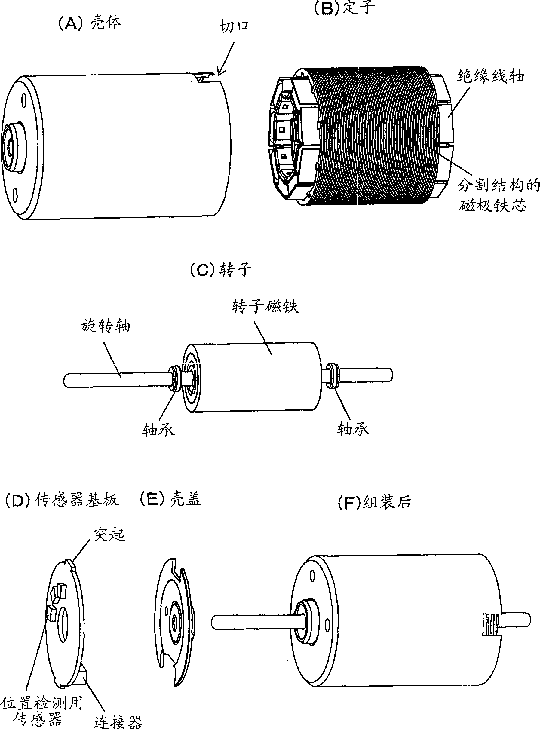
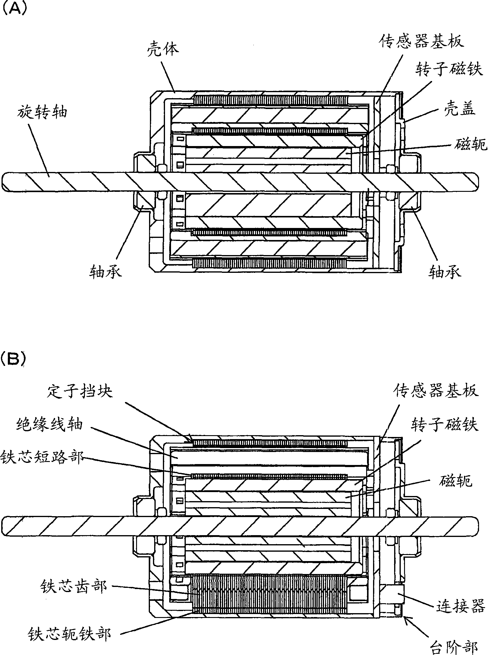
[0022] Hereinafter, the present invention will be described based on examples. figure 1 It is an exploded perspective view of an inner rotor brushless DC motor embodying the present invention. figure 1 (A) represents the casing, (B) represents the stator, (C) represents the rotor, (D) represents the sensor substrate, (E) represents the case cover, and (F) represents the overall assembled structure. figure 2 is a cross-sectional view of the overall structure, figure 2 (A) and (B) in (A) and (B) are figures which are respectively cut with mutually different orthogonal planes.

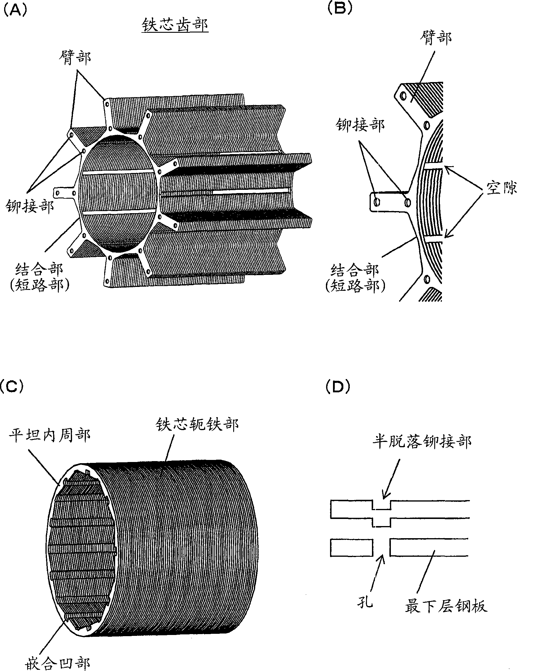
[0023] The motor case is composed of a bottomed hollow cylindrical case made of metal or resin, and a case cover made of metal or resin. The cover is fitted over a stepped portion provided on the inner peripheral portion of the opening of the case. A stator consisting of a pole core and a winding is fixed on the inner wall of the cylindrical housing. The pole core is a split structure divided into ...


PUM


Abstract

The provides a brushless motor of inner rotator and manufacturing method thereof, which will not reduce the circular degree of a core and the winding duty cycle of the space in the groove, to prevent the loss of magnetic flux. A stator core is divided into a core tooth part and a core yoke part to form, wherein the core tooth part is composed of shoulders radially projected according to the number identical to that of the magnetic pole of the stator and combined parts extended in the interconnected form along the inner circumferences of the shoulders, and the core yoke part is cylindrical and pressed to the outer circumference of the tooth part. Clearances are formed on the combined parts. The stator winding is formed by inserting wound insulating spools composed of winding coil on the insulating spools on each shoulder.

Description

technical field [0001] The present invention relates to an inner-rotor brushless motor that switches and controls current flowing to a stator winding by detecting magnetic poles on the rotor side with a position detection sensor on the motor stator side, and a method of manufacturing the same. Background technique [0002] In the inner rotor brushless motor, the position detection sensor mounted on the stator detects the magnetic poles of the magnet provided on the rotor side, thereby switching and controlling the current flowing to the stator winding. In the stator core of such a brushless motor, the slots between the magnetic poles for winding the wires are open toward the inner peripheral side, so it is difficult to wind the wires using a winding machine. [0003] Figure 7 It is a figure which exemplifies the conventional stator core described in patent document 1, (A) shows the top view of a stator core, (B) shows the top view after development. The stator core has an ...

Claims


Application Information

Patent Timeline
Patent Type & Authority Applications(China)
IPC IPC(8): H02K29/08H02K1/14H02K3/18H02K3/28H02K15/02H02K15/04H02K15/06
Inventor 岩崎佑哉
Owner MABUCHI MOTOR
Why Eureka
Try Eureka