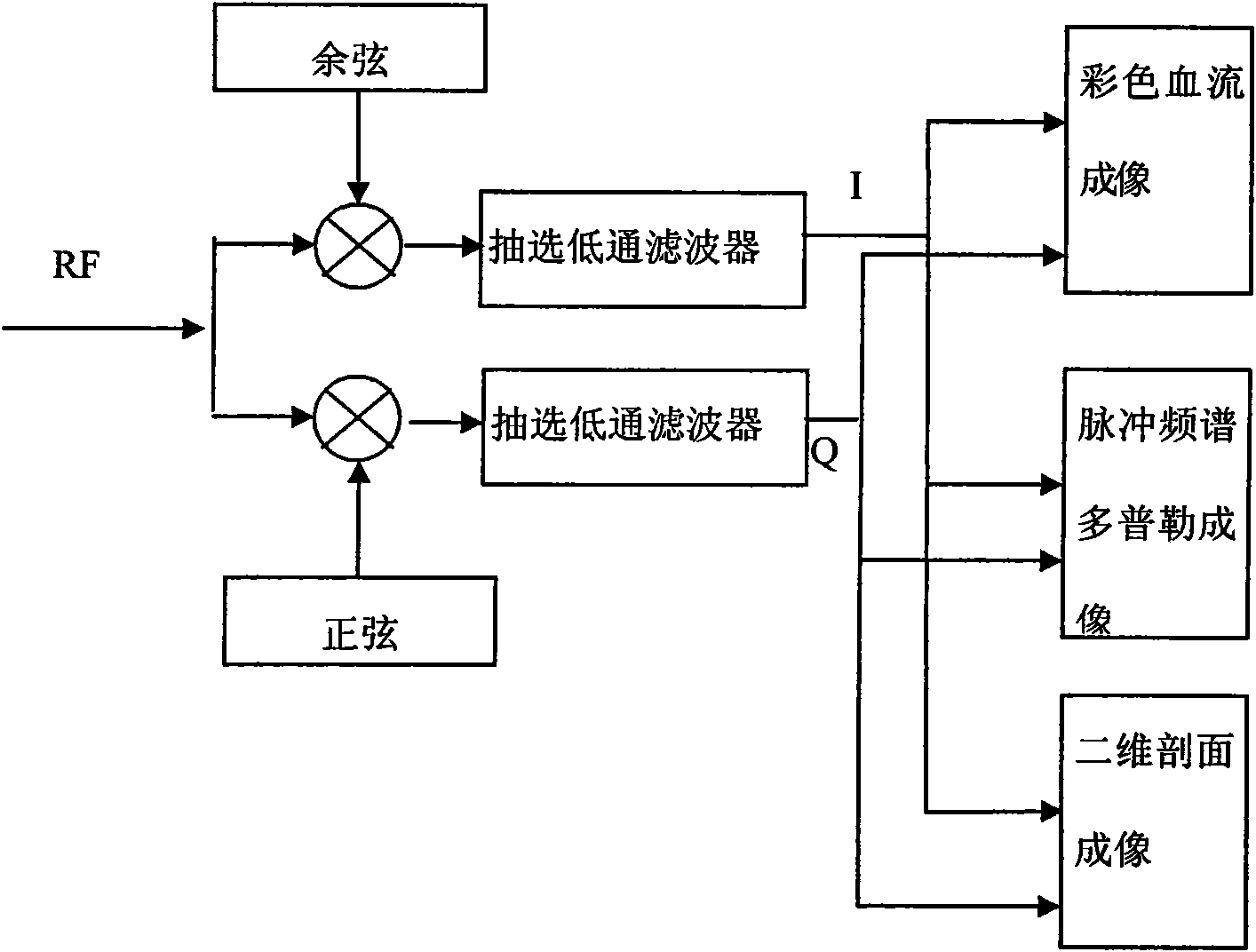
Decimating filtering method and decimating filter
A technology for extracting filtering and extracting factors, which is used in blood flow measurement devices, acoustic wave diagnosis, infrasound wave diagnosis and other directions, which can solve the problems of large depth gear span, inability to meet the fine adjustment and unevenness of ultrasonic image selection ratio.
- Summary
- Abstract
- Description
- Claims
- Application Information
AI Technical Summary
Problems solved by technology
Method used
Image
Examples
Embodiment 1
[0098] It may be assumed that the sampling rate of the input signal x(n) is 40MHz, and now it is necessary to reduce the sampling rate to 160 / 9MHz, and the number of accumulators is L=2, then the decimation ratio of the decimation filter is M=9 / 4, that is, interpolation I=4, extract D=9, according to the formula derived from the above correlation:
[0099] 1) For the first multiply-accumulate item, g m for The integer part of , the last input signal sequence corresponding to the mth output sequence y(m) is x(g m );
[0100] g 0 = 0, so the 0th output y(0) corresponds to the last input sequence as x(0)
[0101] g 1 =2, so the first output y(1) corresponds to the last input sequence as x(2)
[0102] g 2 =4, so the second output y(2) corresponds to the last input sequence as x(4)
[0103] g 3 =6, so the third output y(3) corresponds to the last input sequence as x(6)
[0104] g 4 =9, so the fourth output y(4) corresponds to the last input sequence as x(9)
[0105] g ...
Embodiment 2
[0195] It may be assumed that the sampling rate of the input signal x(n) is 40MHz, and now it is necessary to reduce the sampling rate to 160 / 10MHz, and the number of accumulators is L=2, then the decimation ratio of the decimation filter M=10 / 4, that is, interpolation I=4, extracting D=10, M=10 / 4 is about 5 / 2 after dividing, so T=5, the structure of this decimation filter is the same as Image 6 The structure of the first embodiment shown is similar, and only the filter coefficients are different. The calculation method of the filter coefficients refers to Embodiment 1, each group of filter coefficients includes 5 coefficients, and the first group of filter coefficients is h(0), h(6), h(2), h(8), h( 4), the second group of filter coefficients includes h(10), h(16), h(12), h(18), h(14). Each group of filter coefficients is stored in the coefficient memory 1 and the coefficient memory 2 respectively, and is cyclically output to the multiplication accumulator 1 and the multipli...
Embodiment 3
[0198] Assuming that the sampling rate of the input signal x(n) is 40MHz, it is now necessary to reduce the sampling rate to 160 / 11MHz, and the number of accumulators L=2, then the decimation ratio of the decimation filter M=11 / 4, that is, the interpolation I =4, extracting D=11, M=11 / 4 is still 11 / 4, therefore, T=11.
[0199] Similarly, the structure of the decimation filter is also the same as Image 6 Similar, but the filter coefficients are different. For the calculation method of the coefficients, refer to Embodiment 1. The first group of filter coefficients are in order h(0), h(7), h(3), h(10), h(6), h(2), h(9), h(5), h(1), h(8), h(4) cycle, the second set of filter coefficients are in the order of h(11), h(18), h (14), h(21), h(17), h(13), h(20), h(16), h(12), h(19), h(15) cycle.
PUM
 Abstract
Description
Claims
Application Information
 - R&D
- Intellectual Property
- Life Sciences
- Materials
- Tech Scout
- Unparalleled Data Quality
- Higher Quality Content
- 60% Fewer Hallucinations
Browse by: Latest US Patents, China's latest patents, Technical Efficacy Thesaurus, Application Domain, Technology Topic, Popular Technical Reports.
© 2025 PatSnap. All rights reserved.Legal|Privacy policy|Modern Slavery Act Transparency Statement|Sitemap|About US| Contact US: help@patsnap.com


