
Caulking coupling device, switch and transmission switch

A connecting device and riveting technology, applied in the direction of transmission control, forging/pressing/hammer device, connection, etc., can solve the problems of weakening the riveting connection force, weakening the riveting connection force, etc.

Inactive Publication Date: 2010-12-22
NILES PARTS CO LTD
View PDF11 Cites 0 Cited by
  • Summary
  • Abstract
  • Description
  • Claims
  • Application Information

AI Technical Summary

Problems solved by technology

However, the result has the problem of weakening the forces of the riveted joint
[0019] That is, the problem to be solved is that since the riveting processing portion is formed flatly, when the riveting boundary is made small to prevent cracks from occurring to increase the thickness of the riveting portion, the riveting coupling force is weakened

Method used


Image

  • Caulking coupling device, switch and transmission switch
  • Caulking coupling device, switch and transmission switch
  • Caulking coupling device, switch and transmission switch

Examples


no. 1 example

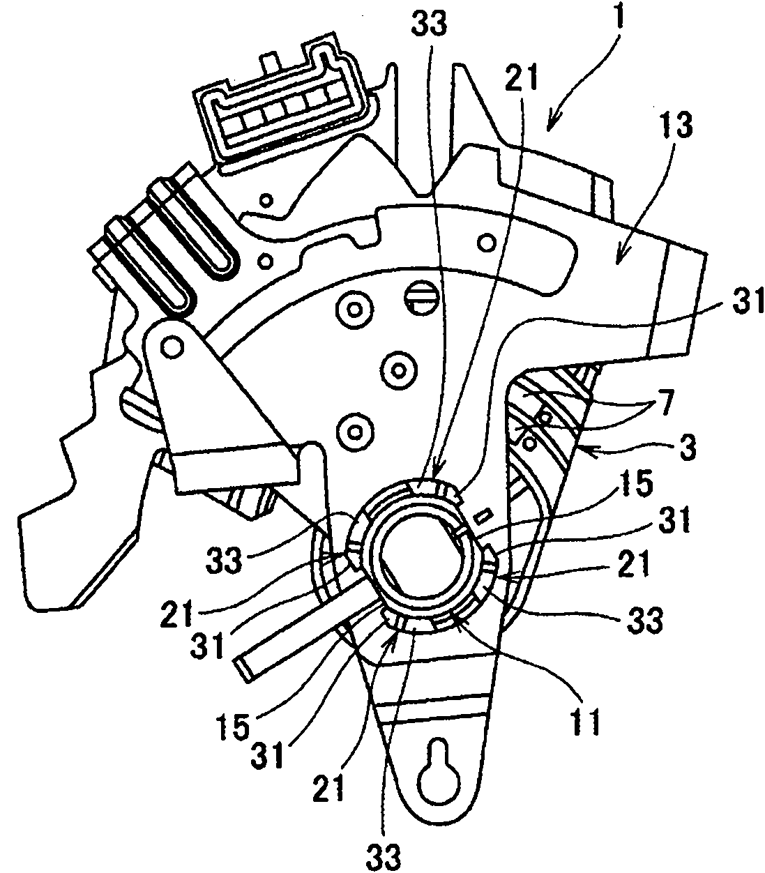
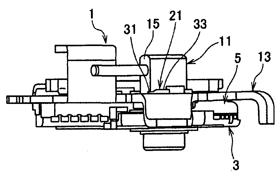
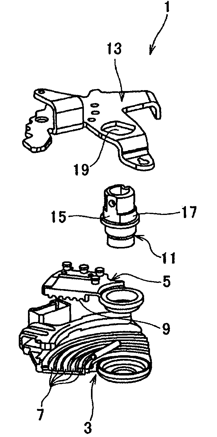
[0077] figure 1 FIG. 3 shows a first embodiment of the invention. figure 1 is a plan view showing the transmission switch. figure 2 is its side view. Figure 3A is an exploded perspective view showing the state before the column member and the stopper plate are assembled. Figure 3B is an exploded perspective view showing a state after assembly. Figure 3C is an exploded perspective view showing a state after riveting coupling of the column member and the stopper plate.

[0078] figure 1 The basic structure of the transmission switch 1 shown in Figure 3 is similar to Figure 8 to Figure 1 0 shown in the transmission switch 101 and the difference lies in the structure of the riveted part. Accordingly, in figure 1 to the transmission switch 1 shown in Figure 3, using the Figure 8 to Figure 1 The code references obtained by subtracting the number 100 from the code in 0 are the same as Figure 8 to Figure 1 The components are the same as those in the transmission sw...


PUM


Abstract

The invention relates to a caulking coupling device, a switch and a transmission switch. The caulking coupling device comprises: a first member; a second member and a punch, wherein: the punch includes a first caulking surface and a second caulking surface as the caulking surface the caulking margins of which axially differ in depth and sequentially formed in a peripheral direction, and includes a regulating surface opposing an outer peripheral surface of the caulking process portion to at least one of the first and second caulking surfaces, which has a deeper caulking margin; and the regulating surface regulates radial fillet movement by caulking of the caulking process portion to promote the fillet movement to the other of the first and second caulking surfaces, which has a less deep caulking margin. The present invention can maintain caulking strength as a whole and prevent occurrence of a crack by eliminating or restricting fillet movement of a caulking portion to a radially outward side.

Description

[0001] Cross References to Related Applications [0002] This application claims priority from Japanese Patent Application JP2009-119278, the disclosure of which is incorporated herein by reference. technical field [0003] The present invention relates to a riveting joint device, a switch and a transmission switch provided for riveting processing of a transmission switch for electrically detecting a shift position in an automatic transmission. Background technique [0004] For example, Figure 8 to 1 0 shows a conventional transmission switch. Figure 8 is a plan view showing a transmission switch of a conventional example, Figure 9 is its side view, Figure 10A is an exploded perspective view showing the state before assembling the column parts and the stopper plate, Figure 10B is an exploded perspective view showing a state after assembly, and Figure 10C is an exploded perspective view showing a state after the column member and the stopper plate are riveted-couple...

Claims


Application Information

Patent Timeline
Patent Type & Authority Applications(China)
IPC IPC(8): B21D39/03F16H63/42
CPCB21K25/00F16H59/105Y10T74/20085Y10T74/2003Y10T29/49934Y10T403/4966Y10T29/52Y10T403/47Y10T74/20636B21D39/02
Inventor 岛田浩幸
Owner NILES PARTS CO LTD
Learn More