Novel cylindrical electromagnetic drive equipment

An electromagnetic drive and equipment technology, applied in the field of new-type drum electromagnetic drive equipment, can solve the problems of increased smoothness of the contact surface between the roller and the groove of the mold, high noise, and wear of the roller and the groove of the mold.

Inactive Publication Date: 2010-12-22
ZUORAN JINGJIANG EQUIP MFG +2
View PDF5 Cites 1 Cited by
  • Summary
  • Abstract
  • Description
  • Claims
  • Application Information

AI Technical Summary

Problems solved by technology

[0002] At present, the furnace tube of the industrial furnace mainly adopts centrifugal casting, and the casting cylinder is mainly driven by the roller driven by the motor. Since it is mainly driven by the friction between the roller and the groove of the cylinder, the noise is very loud. After long-term use Both the roller and the groove of the cylinder are worn to a gre...

Method used


Image

  • Novel cylindrical electromagnetic drive equipment
  • Novel cylindrical electromagnetic drive equipment

Examples


Embodiment Construction

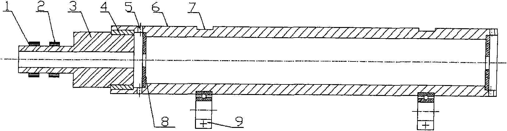
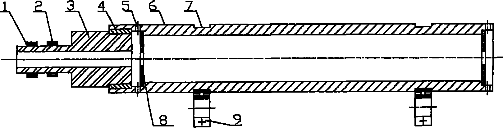
[0007] A new type of cylinder electromagnetic drive equipment, mainly composed of a metal mold cylinder 6, the metal mold cylinder 6 is provided with a linkage pin 4, an end cover fixing pin hole 5, and an end cover 8 is provided through the end cover fixing pin hole, and the metal mold cylinder The supporting bearing 9 corresponding to the size is placed in the original roller groove of the tube, and the bearing groove 7 is also provided on the molded tube. A driving shaft 3 is arranged outside the metal molded cylinder 6 , and a magnetic coil winding 1 is arranged on the driving shaft 3 , and each group of magnetic coils corresponds to the outer magnetic steel 2 .

[0008] The following is an analysis of the production and operation of the new type drum electromagnetic drive equipment:

[0009] Modification of the cold end of the type 1 cylinder

[0010] like figure 1 As shown, the cold end cover of the type cylinder is modified as follows:

[0011] (1) Properly extend th...


PUM


Abstract

The invention discloses novel cylindrical electromagnetic drive equipment, which mainly comprises a metal cylinder. The novel cylindrical electromagnetic drive equipment is characterized in that: a drive shaft is arranged outside the metal cylinder; a magnetic coil winding is arranged on the drive shaft; and each group of magnetic coils corresponds to an outer magnet steel. The invention discloses the manufacturing and installation of an electromagnetic driver, realizes the normal running of the novel cylindrical electromagnetic drive equipment and fulfils the aims of improving driving efficiency, and reducing noise, abrasion and slip frequency. The cylindrical electromagnetic drive equipment has the characteristics of low cost, excellent performances and the like, improves the running efficiency of a centrifuge, reduces the noise of a production environment, and has great popularization value.

Description

technical field [0001] The novel cylinder electromagnetic drive device of the invention belongs to the field of centrifugal casting. Background technique [0002] At present, the furnace tube of the industrial furnace mainly adopts centrifugal casting, and the casting cylinder is mainly driven by the roller driven by the motor. Since it is mainly driven by the friction between the roller and the groove of the cylinder, the noise is very loud. After long-term use Both the roller and the groove of the molded cylinder are worn to a greater extent. The wear causes the centrifuge to lose its dynamic balance, and the wear causes the smoothness of the contact surface between the roller and the groove of the mold cylinder to increase, causing a slip when the mold cylinder rotates, which will cause the actual speed of the mold cylinder to decrease, and the quality of the centrifugal casting product Certainly affected. Contents of the invention [0003] The purpose of the present ...

Claims


Application Information

Patent Timeline
IPC IPC(8): B22D13/10
Inventor 马利平展益彬马利峰毛凯田
Owner ZUORAN JINGJIANG EQUIP MFG
Why Eureka
Try Eureka