Crane lifting mechanism

A lifting mechanism and crane technology, applied in the direction of clockwork mechanism, load block, load hanging components, etc., can solve the problems of frame fatigue damage, laborious, time-consuming maintenance of fixed pulley blocks, etc., to achieve convenient maintenance and maintenance, The effect of increasing the lifting height and improving the stress condition

Inactive Publication Date: 2010-12-22
SHANQI HEAVY MACHINERY
View PDF3 Cites 8 Cited by
  • Summary
  • Abstract
  • Description
  • Claims
  • Application Information

AI Technical Summary

Problems solved by technology

[0003] 1. It is time-consuming and labor-intensive to overhaul the fixed pulley block. Since the fixed pulley block is located under the reel and limited by space, it is very difficult to maintain or replace the pulley block. It is even necessary to disassemble the reel and other components, which increases the workload of workers;
[0004] 2. The lifting height of heavy objects is limited. The lifting height of heavy objects is limited by the position he

Method used


Image

  • Crane lifting mechanism
  • Crane lifting mechanism
  • Crane lifting mechanism

Examples


Embodiment Construction

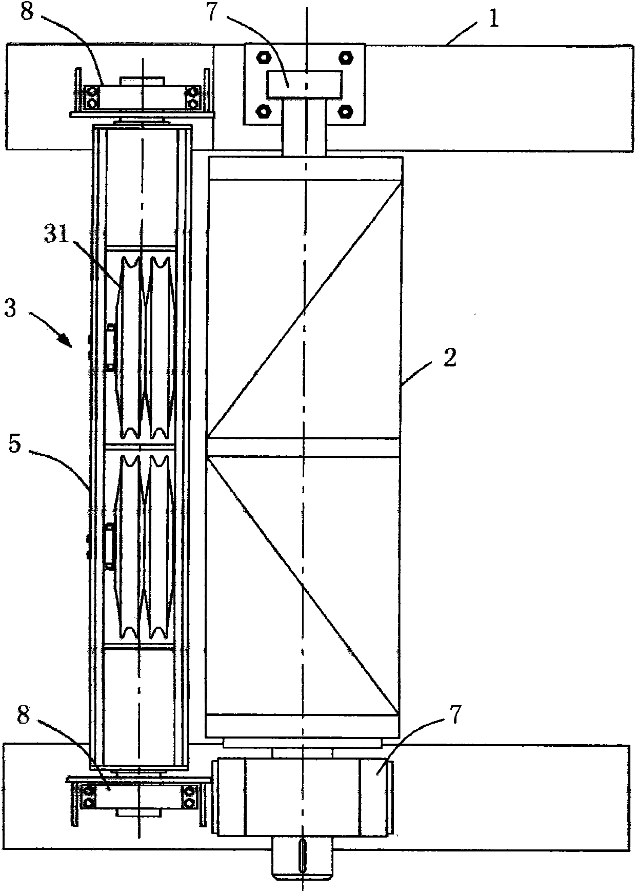
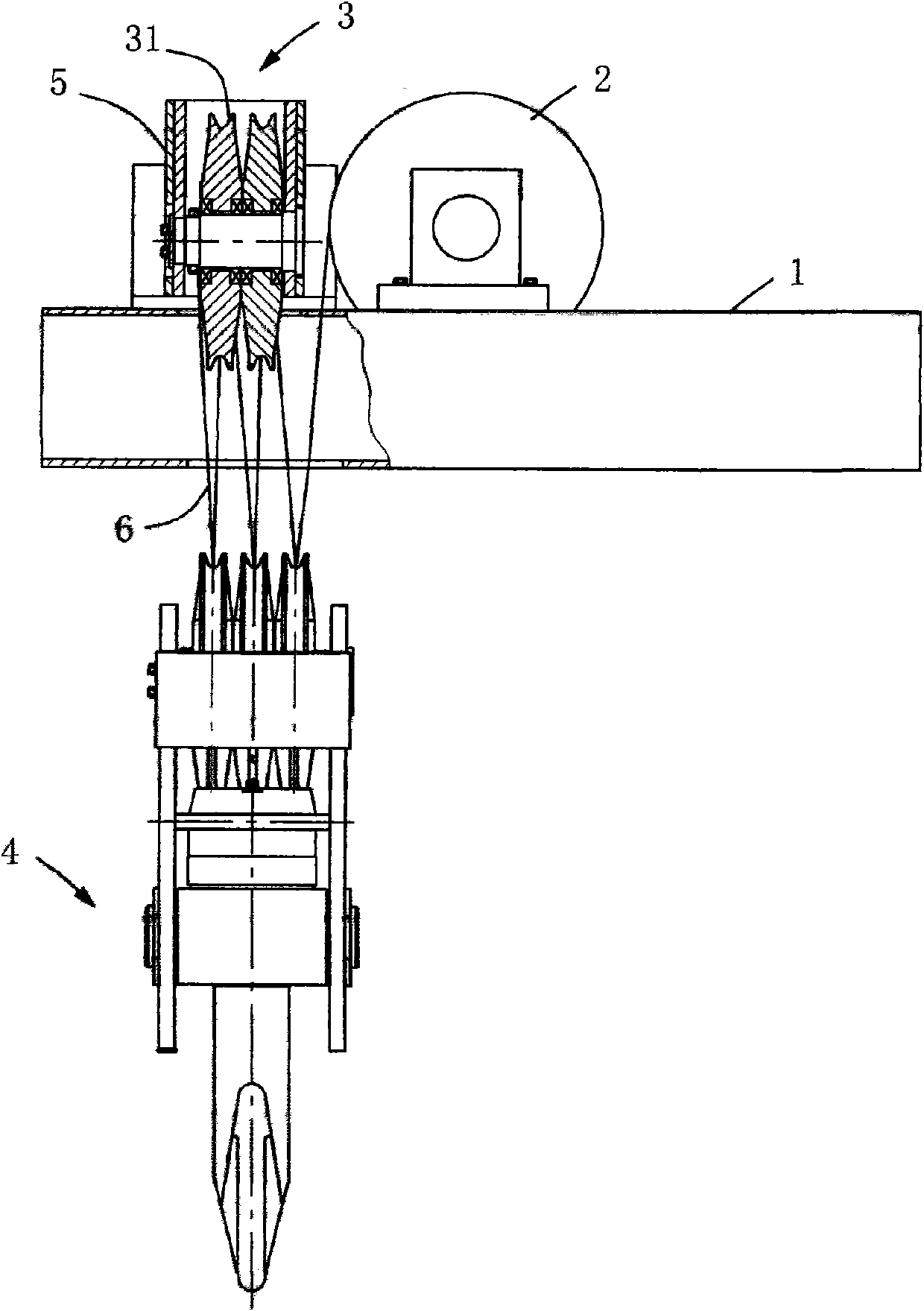
[0017] like figure 1 and figure 2 As shown, a crane lifting mechanism mainly includes a reel 2 and a fixed pulley block 3, the reel 2 is rotatably mounted on the upper end surface of the vehicle frame 1, the fixed pulley block 3 is connected to the hook assembly 4 through a rope 6, One end of the rope 6 is fixed on the reel 2, and the other end is fixed on the fixed pulley block 3, the rope 6 is wound between the fixed pulley block 3 and the movable pulley block of the hook assembly 4, driven by the power of the reducer, the reel 2 rotates , so that the rope 6 is wound on the reel 2, and the hook assembly 4 drives the weight up. The lifting mechanism also includes a pulley beam 5 for installing the fixed pulley block 3, and the fixed pulleys 31 of the fixed pulley block 3 are all rotatably mounted on the pulley beam 5, and the pulley beam 5 is installed on the vehicle. On the upper end face of the frame 1, the pulley beam 5 is hinged on the frame 1 through two pulley beam b...


PUM


Abstract

The invention discloses a crane lifting mechanism belonging to the technical field of cranes. The crane lifting mechanism mainly comprises a winding drum and a fixed pulley block, wherein the winding drum is rotatably installed on the upper end surface of a frame through two bearing seats; the fixed pulley block is connected with a hook component through a rope; one end of the rope is fixed on the winding drum; the lifting mechanism also comprises a pulley beam for installing the fixed pulley block; and the pulley beam is installed on the upper end surface of the frame. In the invention, by changing the installing position of the fixed pulley block, the fixed pulley block can be maintained conveniently, and simultaneously, the lifting height of a heavy object is increased.

Description

technical field [0001] The invention relates to the technical field of cranes, in particular to a lifting mechanism of a crane. Background technique [0002] When hoisting heavy objects, the crane relies on the hoisting mechanism to connect the hook with the rope to lift the heavy objects. The traditional hoisting mechanism includes a reel installed on the frame of the trolley and a fixed pulley block rotatably installed on the frame. The installation position of the pulley block is located on the frame under the drum. Although this structure makes the overall structure of the crane compact, it has the following disadvantages: [0003] 1. It is time-consuming and labor-intensive to overhaul the fixed pulley block. Since the fixed pulley block is located under the reel and limited by space, it is very difficult to maintain or replace the pulley block. It is even necessary to disassemble the reel and other components, which increases the workload of workers; [0004] 2. The l...

Claims


Application Information

Patent Timeline
IPC IPC(8): B66C11/16B66D1/00
Inventor 粘来勇李明春李呈龙王丰顺陈砚涛
Owner SHANQI HEAVY MACHINERY
Why Eureka
Try Eureka