Fuel control strategy for heating a catalyst

A fuel control module and catalyst technology, applied in electrical control, engine control, electronic control of exhaust treatment devices, etc., can solve problems such as limited reaction capacity of catalysts

Inactive Publication Date: 2010-12-22
GM GLOBAL TECH OPERATIONS LLC
View PDF4 Cites 6 Cited by
  • Summary
  • Abstract
  • Description
  • Claims
  • Application Information

AI Technical Summary

Problems solved by technology

Therefore, if the catalyst temperature is lower than the light-off temperature when the engine is started (for example, key start), the catalyst's ability to respond may be limited

Method used


Image

  • Fuel control strategy for heating a catalyst
  • Fuel control strategy for heating a catalyst
  • Fuel control strategy for heating a catalyst

Examples


Embodiment Construction

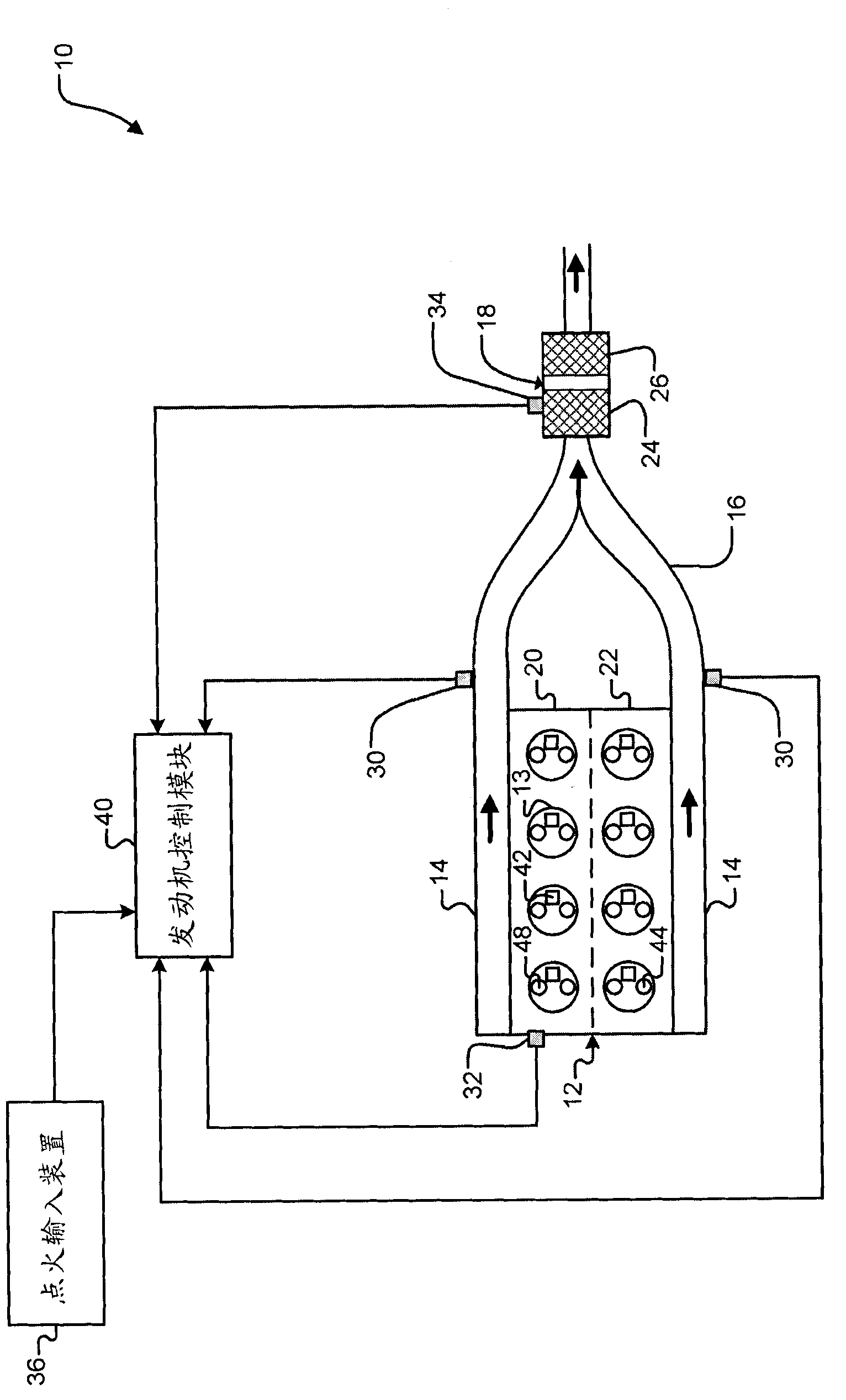
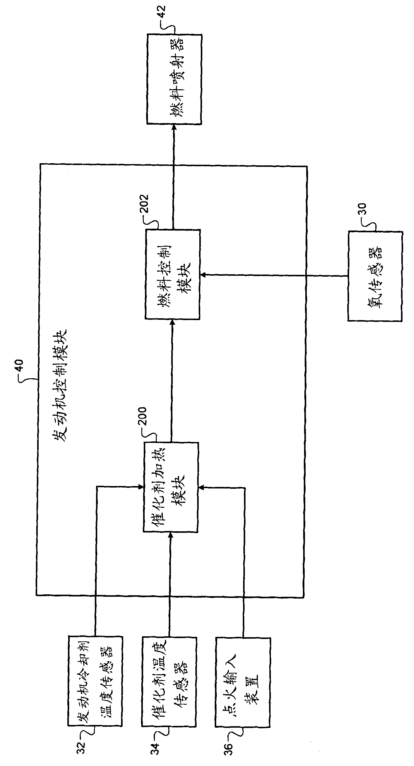
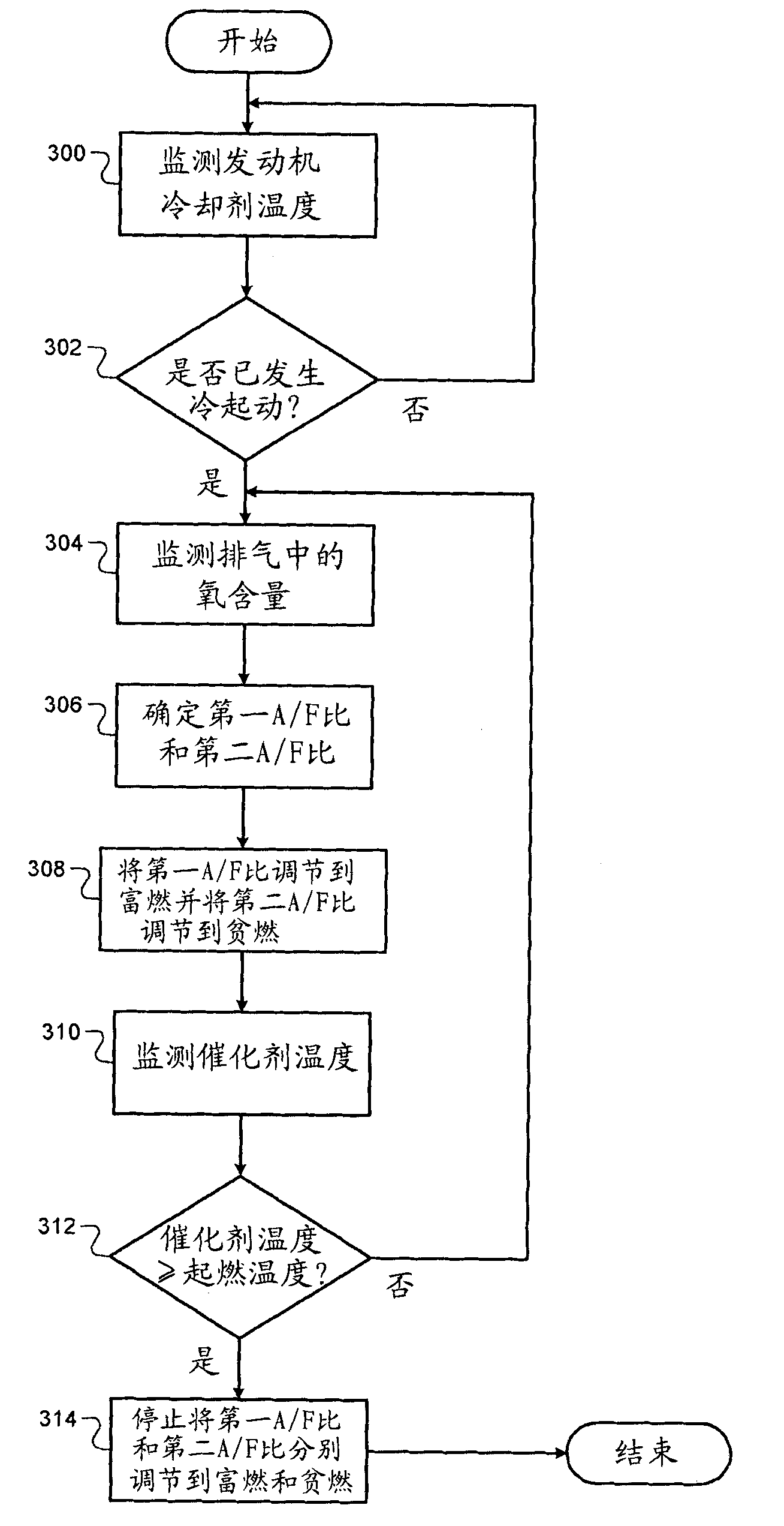
[0039] The following description is merely exemplary in nature and is not intended to limit the invention, its application or uses in any way. For purposes of clarity, the same reference numbers will be used in the drawings to refer to like parts. As used herein, the phrase at least one of A, B, and C should be construed to mean a logical "A or B or C" using a non-exclusive logical or. It should be understood that steps within a method may be executed in different order without altering the principles of the present invention.

[0040] As used herein, the term "module" refers to an application-specific integrated circuit (ASIC), an electronic circuit, a processor (shared, dedicated, or grouped) and memory, combinational logic, that executes one or more software or firmware programs circuits, and / or other suitable components that provide the described functions.

[0041] The fuel control system and method of the present invention can operate the engine in a catalyst heating m...


PUM


Abstract

The invention relates to a fuel control strategy for heating a catalyst. Concretely the invention provides a control system for an engine, comprising a catalyst heat module and a fuel control module, wherein the engine comprises N cylinders in first and second banks includes a catalyst heat module and a fuel control module. N is an integer greater than two. The catalyst heat module selectively operates the engine in a catalyst heat mode to heat a catalyst. The fuel control module, throughout a fuel injection sequence for each of the N cylinders, adjusts a first air / fuel (A / F) ratio for the first bank to a rich value and adjusts a second A / F ratio for the second bank to a lean value.

Description

technical field [0001] The present invention relates to a fuel control system and method for heating a catalyst in an exhaust system. Background technique [0002] The background description provided herein is for the purpose of generally presenting the context of the disclosure. A portion of the inventor's work is described in the Background section, and this, and aspects of this description that were not otherwise prior art at the time of filing the application, are neither expressly nor impliedly considered prior art to the invention . [0003] The engine combusts an air / fuel mixture to produce drive torque for the vehicle. Air is drawn into the engine through the throttle valve and intake manifold. Fuel is provided through one or more fuel injectors. The air / fuel mixture is combusted in one or more cylinders of the engine. Combustion of the air / fuel mixture may be initiated by, for example, compression provided by a piston and / or spark provided by a spark plug. Com...

Claims


Application Information

Patent Timeline
Patent Type & Authority Applications(China)
IPC IPC(8): F01N9/00B01D53/88F01N3/20
CPCB01D53/9454F02D2200/021F02D2200/0802F01N3/2006Y02T10/22F02D41/0082F01N13/107Y02T10/26Y02T10/47F01N2430/06F01N9/00F02D41/025B01D53/9495F02D41/0255Y02T10/12Y02T10/40
Inventor H·G·桑托索E·V·冈策B·N·鲁斯B·斯波恩
Owner GM GLOBAL TECH OPERATIONS LLC
Why Eureka
Try Eureka