
Dual-cavity dual-drive piezoelectric stack pump

A piezoelectric stacking, dual-drive technology, applied in pumps, machines/engines, pumps with flexible working elements, etc., can solve the problems of small cavity volume, weak carrying capacity, small output flow, etc., and achieve good response characteristics , strong bearing capacity, and the effect of large pressure output

Inactive Publication Date: 2010-12-22
JILIN UNIV
View PDF4 Cites 24 Cited by
  • Summary
  • Abstract
  • Description
  • Claims
  • Application Information

AI Technical Summary

Problems solved by technology

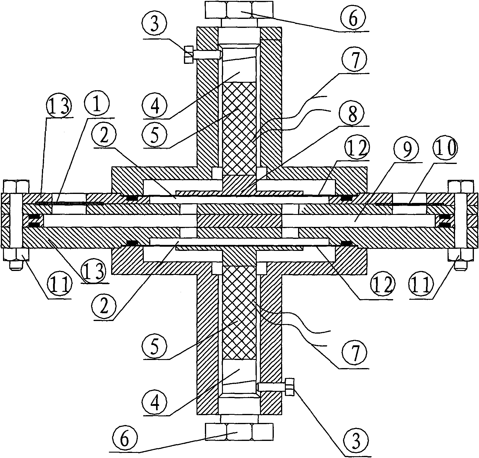
[0003] The invention provides a double-cavity double-drive piezoelectric stack pump to solve the problem of low voltage, low output precision, small cavity volume, small output flow rate and relatively weak carrying capacity of the piezoelectric vibrator of the wafer piezoelectric pump. problem, the present invention is achieved through the following technical solutions: the coarse-adjustment pre-tightening nuts and fine-tuning pre-tightening nuts on both sides are threadedly connected to the stack support body respectively, and the piezoelectric stacks on both sides are fixedly bonded to the stacking seat, Through the contact connection between the inclined block pre-tightening device and the coarse adjustment pre-tightening nut, the piezoelectric stack is connected to the stack wire, the vibrating diaphragm on both sides is fixedly bonded to the stack seat, and the vibrating diaphragm and the valve seats on both sides are respectively formed. The cavity on both sides, the inlet one-way valve is fixedly connected with the valve seat, the outlet one-way valve is fixedly connected with the valve seat, respectively connected with the flow channel, the valve seats on both sides are fixedly connected by bolts; the inlet one-way valve, the outlet The one-way valve adopts the internal distribution cantilever beam valve

Method used


Image

  • Dual-cavity dual-drive piezoelectric stack pump
  • Dual-cavity dual-drive piezoelectric stack pump

Examples


Embodiment Construction

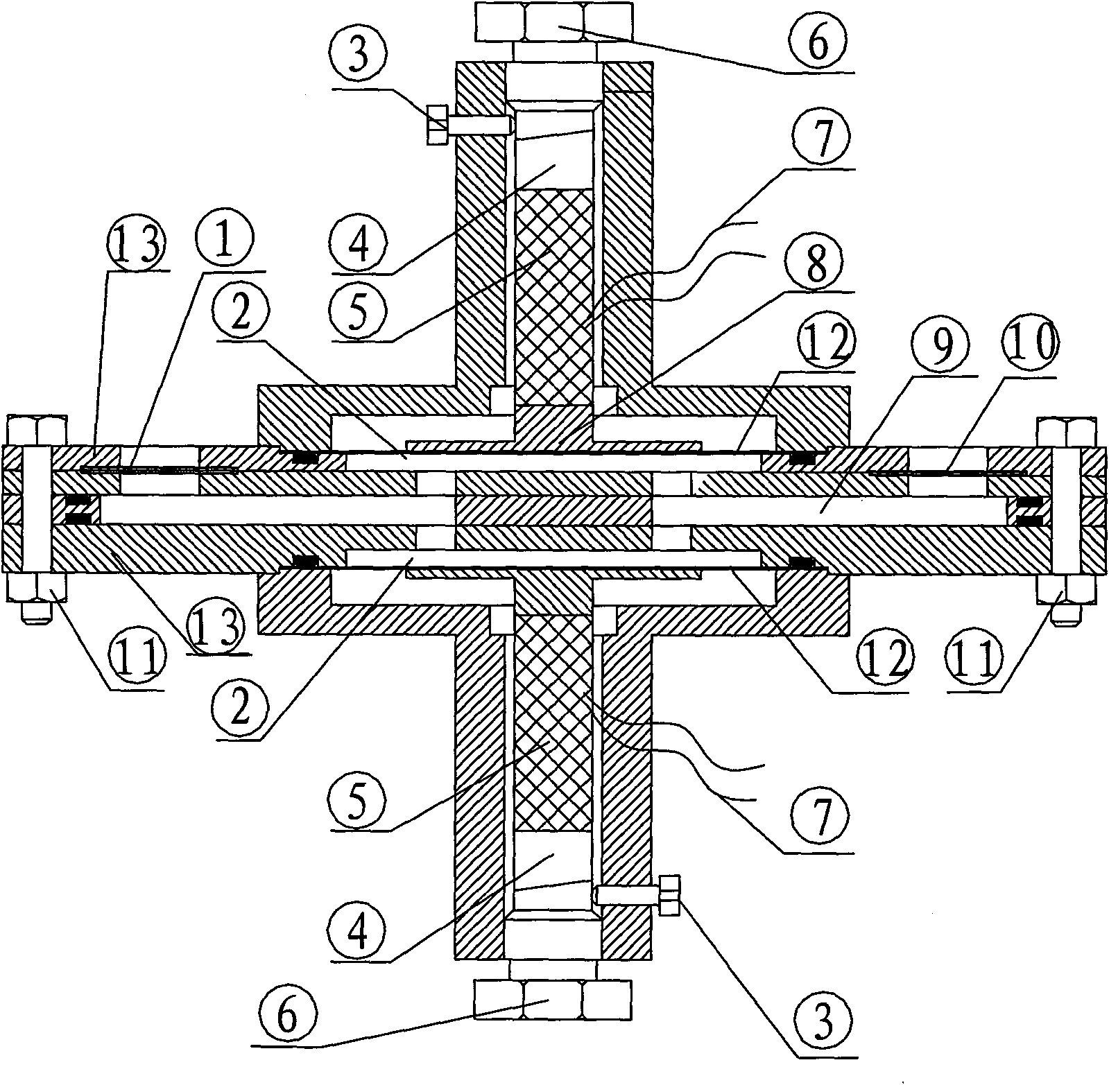
[0012] The coarse-adjustment pre-tightening nut 6 and the fine-tuning pre-tightening nut 3 on both sides are threadedly connected with the stack support body respectively, the piezoelectric stack 5 on both sides is fixedly bonded to the stacking seat 8, and the inclined block pre-tightening device 4 is connected to the coarse Adjust the pre-tightening nut contact connection, the piezoelectric stack is connected to the stack wire 7, the vibrating diaphragm 12 on both sides is fixedly bonded to the stack seat 8, and the vibrating diaphragm 12 and the valve seat 13 on both sides respectively form a The cavity 2, the inlet one-way valve 1 is fixedly connected to the valve seat, the outlet one-way valve 10 is fixedly connected to the valve seat, and respectively connected to the flow channel 9, and the valve seats on both sides are fixedly connected by bolts 11.

[0013] Among them, the inlet one-way valve and the outlet one-way valve adopt the inner distribution cantilever beam val...


PUM


Abstract

The invention relates to a dual-cavity dual-drive piezoelectric stack pump, and belongs to the field of micro-electrical mechanics. Rough-adjustment pre-tightening nuts and fine-adjustment pre-tightening nuts on the two sides are respectively threaded with a stack supporting body; piezoelectric stacks on the two sides are fixedly adhered to a stack seat and are connected with the rough-adjustment pre-tightening nuts through inclined block pre-tightening devices in a contact way; the piezoelectric stacks are connected with a stack through a lead wire; vibrating diaphragms on the two sides are fixedly adhered to the stack seat; the vibrating diaphragms and valve seats on the two sides form cavities on the two sides respectively; inlet check valves are fixedly connected with the valve seats; outlet check valves are fixedly connected with the valve seats and are connected with a flow channel respectively; and the valve seats on the two sides are fixedly connected with each other through bolts. The dual-cavity dual-drive piezoelectric stack pump has the following advantages of: novel structure, high output flow rate, strong bearing capacity and higher pressure output, and simultaneously has good controllability and output stability.

Description

technical field [0001] The invention belongs to the field of micro-electronic machinery, in particular to a piezoelectric driver. Background technique [0002] Piezoelectric actuator is a new control and drive micro-actuator based on wave principle. It uses the inverse piezoelectric effect of piezoelectric elements to convert electrical energy into a new type of drive device that is mechanical. Piezoelectric pump is a new type of fluid driver based on piezoelectric drive. Compared with traditional pumps and other micropumps driven by other methods, piezoelectric pump has simple structure, small size, light weight, low energy consumption, no noise, no electromagnetic Interference, can control the output of small flow according to the applied voltage or frequency. Although its invention and development have only a history of more than 20 years, it has been widely used in the fields of aerospace vehicles, robots, automobiles, medical equipment, biological genetic engineering,...

Claims


Application Information

Patent Timeline
IPC IPC(8): F04B43/04
Inventor 刘建芳孙威刘爽范尊强杨志刚
Owner JILIN UNIV
Learn More