Composite self-lubricating bearing

A self-lubricating bearing, compound technology, applied in the direction of bearings, bearing components, shafts and bearings, can solve the problems of self-lubricating bearing bearing capacity limitation, difficult oil supply, weak structure, etc., to meet the needs of industrial applications, Flexible design and application, optimizing the effect of the limit of use

Active Publication Date: 2010-12-22
NEWCERA TECH
View PDF0 Cites 3 Cited by
  • Summary
  • Abstract
  • Description
  • Claims
  • Application Information

AI Technical Summary

Problems solved by technology

[0002] In order to make the operation between the bearing and the rotating shaft smooth, and to avoid abnormal friction and heat generation, it is usually necessary to frequently add additional lubricants (lubricant), such as lubricating oil with low viscosity and high viscosity Lubricating grease (gerase) and lubricants containing solid lubricating particles, etc., in order to continuously form a tribology interface (tribology interface) between the inner wall of the shaft hole and the outer wall of the rotating shaft core that is sufficient to carry the load of the shaft core; however, due to frequent Adding additional lubricating medium is not only labor-intensive but also inconvenient. If the lubricating medium is not replenished in time, it will quickly cause excessive friction and heat generation and damage to the bearing and shaft core in the non-lubricated state
The existing self-lubricating bearings generally use lubricating oil to form the lubricating interface between the shaft hole and the shaft core. However, due to the thin lubricating oil film formed, the carrying capacity of the existing self-lubricating bearings is limited. The viscosity at high temperature will become lower, resulting in a thinner lubricating oil film. At this time, if the bearing must operate at high speed or high load, the shaft core may push the lubricating oil film on the wall of the shaft hole. The shaft core directly collides with the wall of the shaft hole at a high speed, thus causing excessive wear and heating of the existing self-lubricating bearing, which will eventually cause noise, shaft scraping, and hole expansion of the self-lubricating bearing to accelerate damage
[0003] Conversely, since the viscosity of lubricating grease and lubricants containing solid lubricating particles is us...

Method used


Image

  • Composite self-lubricating bearing
  • Composite self-lubricating bearing
  • Composite self-lubricating bearing

Examples


Embodiment Construction

[0020] The above and other technical features and advantages of the present invention will be described in more detail below in conjunction with the accompanying drawings.

[0021] Refer to the following Figure 1 to Figure 8 , to further illustrate the composite self-lubricating bearing of the present invention.

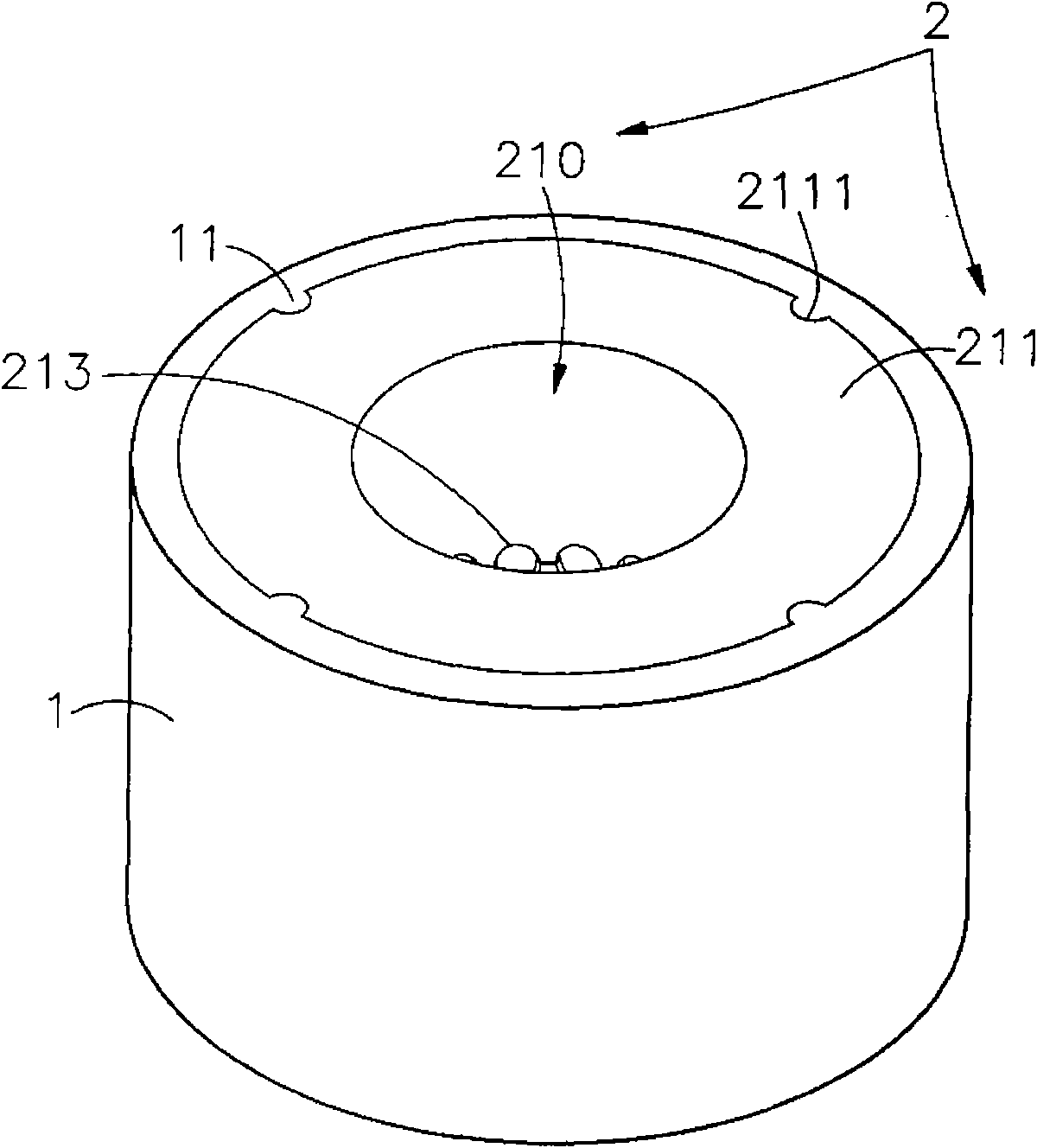
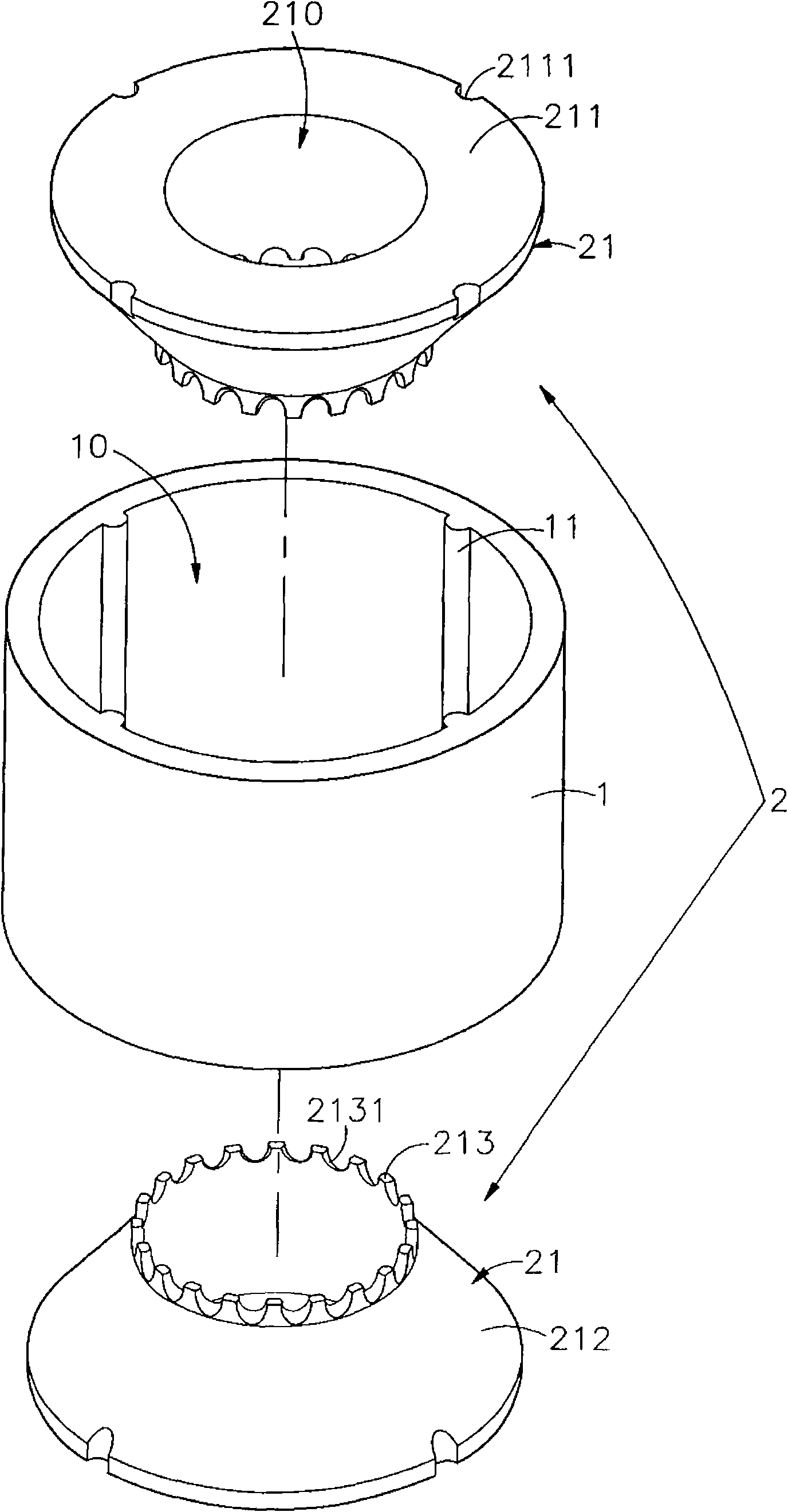
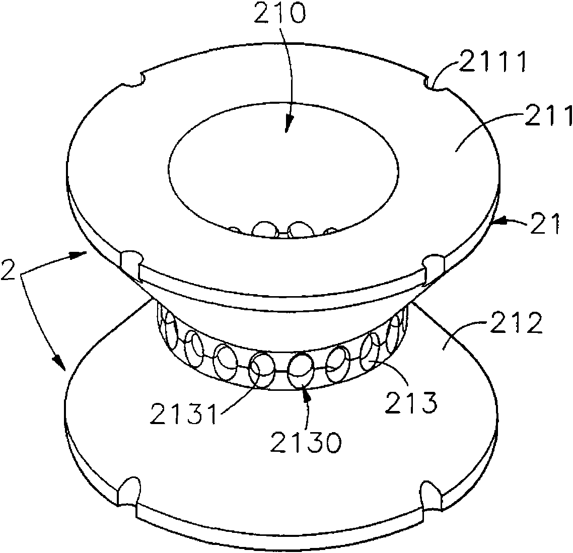
[0022] see Figure 1 to Figure 5 As shown, they are the three-dimensional appearance view, the three-dimensional exploded view, the combined schematic diagram of the bearing unit, the assembly sectional view and the assembly sectional view assembled with the shaft core of the first embodiment of the present invention; the composite self-lubricating bearing is composed of a housing 1 and The bearing set consists of 2, of which:

[0023] The housing 1 is a hollow cylinder penetrating in the axial direction to form an accommodating space 10, which is made of dense solid material or porous material, and the wall surface of the accommodating space 10 is provided with a...


PUM


Abstract

The invention relates to a composite self-lubricating bearing which comprises a bearing group and a shell, wherein the bearing group is formed by assembling at least one bearing unit, and the bearing unit is provided with an axially-perforative axial hole in which an axial core passes through; the shell is a hollow tube body which is used for sleeving on the outer edge of the bearing group along the axial core direction in a sealing way, and at least one storage tank for storing a lubricating medium is defined by the bearing group and the shell. At least one microgap runner communicated with the axial hole is arranged round the storage tank so as to continuously supply the lubricating medium. The lubricating medium exerts the efficacy of high-quality lubrication between the axial core and the axial hole.

Description

technical field [0001] The invention relates to a composite self-lubricating bearing, in particular to a composite self-lubricating bearing which can automatically replenish lubricating medium to achieve enhanced grinding effect. Background technique [0002] In order to make the operation between the bearing and the rotating shaft smooth, and to avoid abnormal friction and heat generation, it is usually necessary to frequently add additional lubricants (lubricant), such as lubricating oil with low viscosity and high viscosity Lubricating grease (gerase) and lubricants containing solid lubricating particles, etc., in order to continuously form a tribology interface (tribology interface) between the inner wall of the shaft hole and the outer wall of the rotating shaft core that is sufficient to carry the load of the shaft core; however, due to frequent Adding additional lubricating medium is not only labor-intensive but also inconvenient. If the lubricating medium is not repl...

Claims


Application Information

Patent Timeline
IPC IPC(8): F16C17/00F16C33/10
Inventor 刘汉卿黄隆伟
Owner NEWCERA TECH
Why Eureka
Try Eureka