Piloted valve, particularly proportional throttle valve

A pilot control valve, pilot control technology, applied in valve details, valve device, valve operation/release device, etc., can solve problems such as excess force of the magnet system, achieve stable operation characteristics, and eliminate the effect of sudden movement

Inactive Publication Date: 2010-12-22
HYDAC FLUITECHNIK GMBH
View PDF1 Cites 18 Cited by
  • Summary
  • Abstract
  • Description
  • Claims
  • Application Information

AI Technical Summary

Problems solved by technology

However, under the condition of constant large magnetic force, the force excess of the magnet system will be generated

Method used


Image

  • Piloted valve, particularly proportional throttle valve
  • Piloted valve, particularly proportional throttle valve
  • Piloted valve, particularly proportional throttle valve

Examples


Embodiment Construction

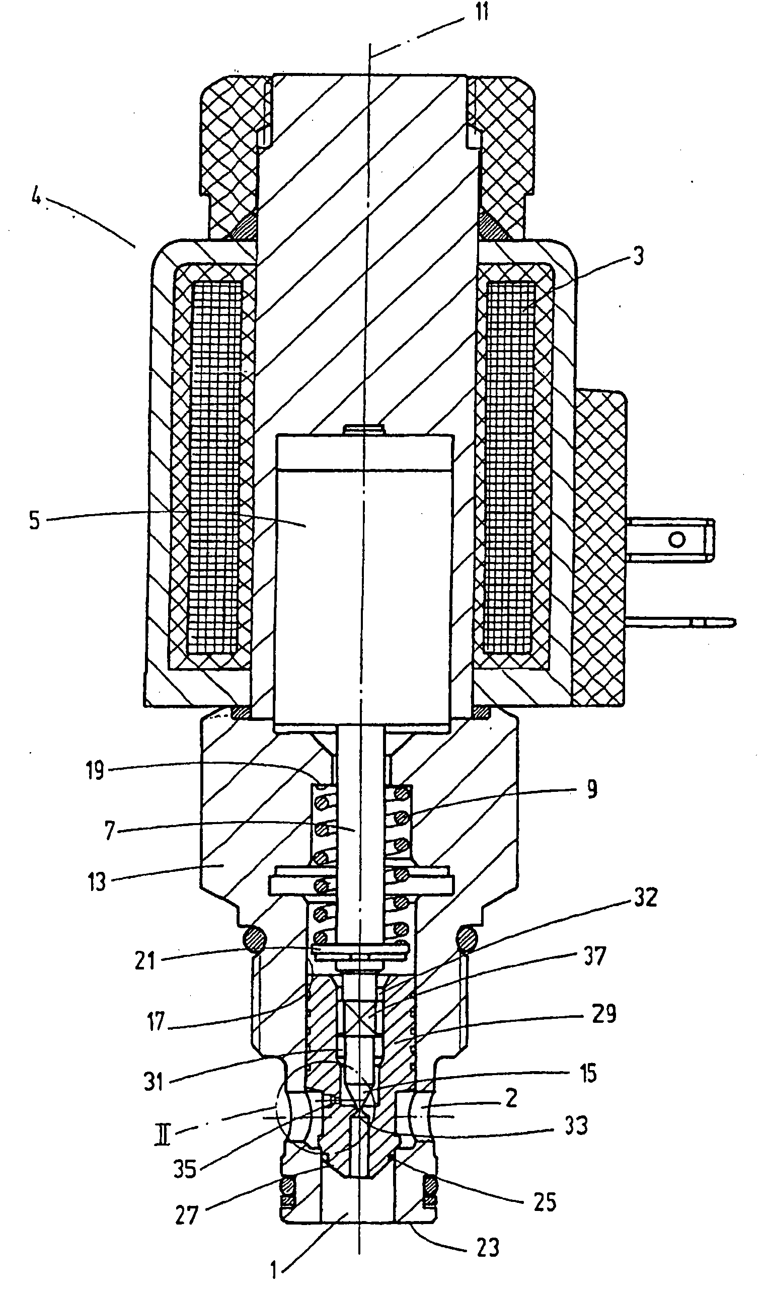
[0026] The known pilot-controlled proportional throttle valve in the form of cooperation according to FIG. 1 is provided with an electrically controllable magnet system 4 . Magnet systems of this type for controlling valves are well known in the prior art (DE 4416279 A1), wherein an armature 5 can be controlled by means of an actuating coil 3 of the magnet system 4 . In the embodiment shown, the magnet system 4 is designed as a so-called pull-in displacement-controlled proportional magnet, which, viewed in the direction of view in FIG. Element 7 moves from bottom to top. In the de-energized state, the armature 5 and thus the actuating element 7 are reset downwards via an energy store formed by a compression spring 9 , that is to say, with respect to the longitudinal axis 11 , are brought into a closed position with the throttle valve corresponding axial position.

[0027]The housing of the magnet system 4 is connected to a valve housing 13 in a sealed condition, the actuatin...


PUM


Abstract

The invention relates to a piloted valve, particularly a piloted proportional throttle valve, having a valve piston (29) displaceably guided in the longitudinal direction in a valve housing (13) having a fluid inlet (2) and outlet (1), the front side (27) whereof can be pressurized against a main valve seat (25) by fluid pressure acting on the back side thereof, having a pilot valve device comprising an actuating member (7) displaceable in the longitudinal direction by means of an electrically actuatable magnet system (4), working together with a pilot valve seat (37) in a bore (17) of the valve piston (29) connecting the back side thereof to the fluid outlet (1) on the front side of the piston, in order to reduce the fluid pressure on the back side of the piston (29) for an opening motion when the pilot valve seat (33) is released, a flow baffle device (39) being disposed between the back side of the piston and the fluid inlet (2) of the housing (13) for building up the fluid pressure pressurizing the piston (29) against the closed position thereof by introducing pilot fluid, characterized in that the flow baffle device (39) comprises a device for performing filtration, preferably gap filtration, of the pilot fluid.

Description

technical field [0001] The invention relates to a pilot-controlled valve, in particular a pilot-controlled proportional throttle valve, with a valve piston and a pilot-controlled valve device, the valve piston being in a valve housing with a fluid inlet and a fluid outlet along its length Directionally guided and pretensionable by fluid pressure acting on its rear side with its front side towards a main valve seat, the pilot control valve device has a lengthwise directionally displaceable operating element that cooperates with a pilot control seat in a bore in the valve piston connecting its back with a fluid outlet on the front of the piston so that when the pilot control seat is released Reducing the fluid pressure at the back of the piston for the opening movement, wherein in order to build up the fluid pressure pre-tensioning the piston towards its closed position by supplying pilot control fluid, there is a flow restriction between the back of the piston and the fluid inl...

Claims


Application Information

Patent Timeline
Patent Type & Authority Applications(China)
IPC IPC(8): F16K31/40
CPCF16K31/408Y10T137/87209
Inventor M·比尔P·布鲁克
Owner HYDAC FLUITECHNIK GMBH
Why Eureka
Try Eureka