
Pump For Delivering A Fluid Product

a technology for fluid products and pumps, applied in the direction of positive displacement liquid engines, liquid fuel engines, instruments, etc., can solve the problems of piston sealing and wear problems, reduce tolerances, and reduce the production efficiency of pumps, so as to improve the aspiration capacity of pumps, improve the deformation capacity of the base, and improve the pinching of the free end of the sleeves

Active Publication Date: 2008-05-22
ALBEA LE TREPORT
View PDF17 Cites 14 Cited by
  • Summary
  • Abstract
  • Description
  • Claims
  • Application Information

AI Technical Summary

Benefits of technology

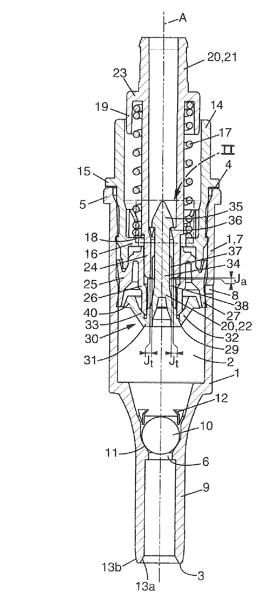
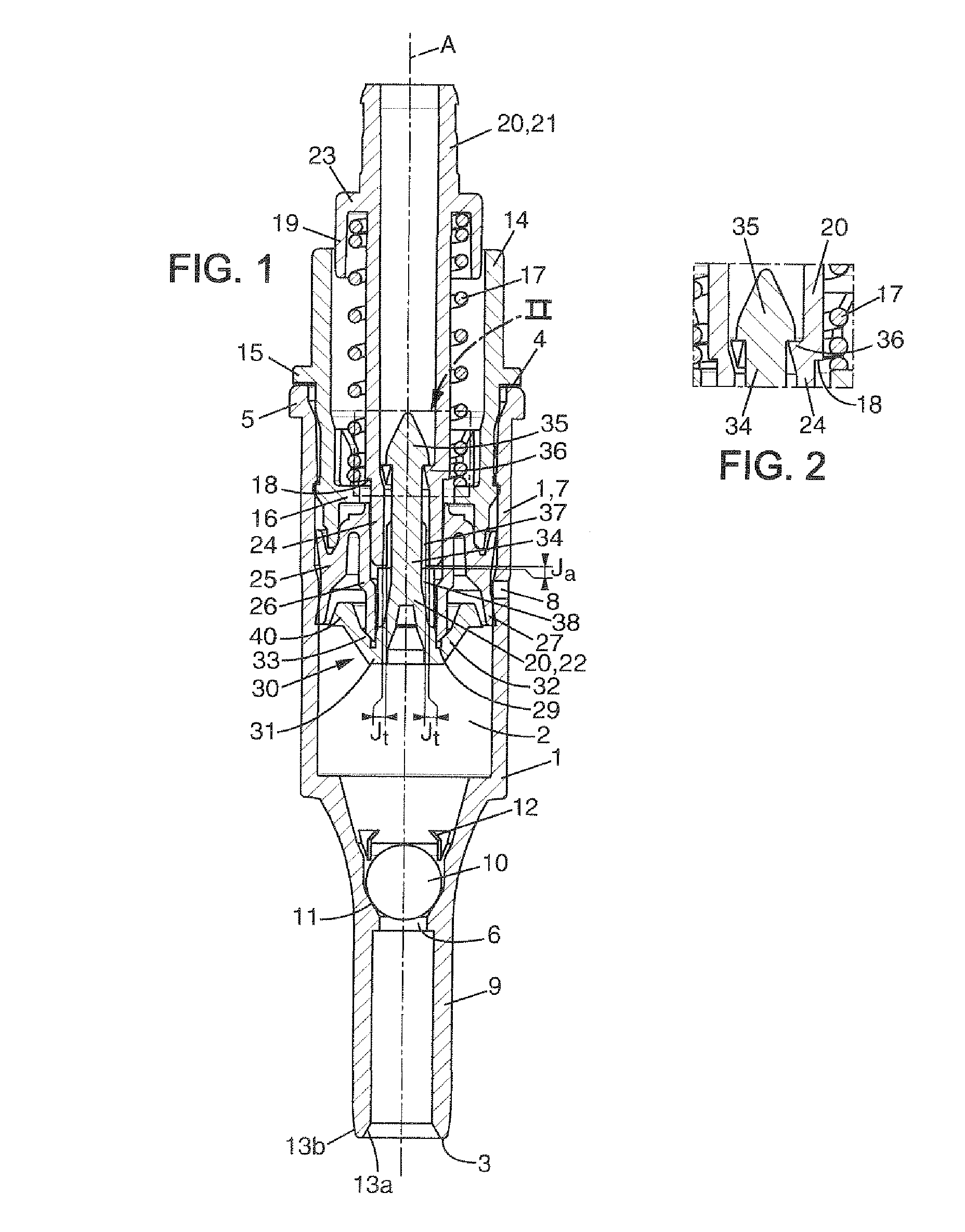
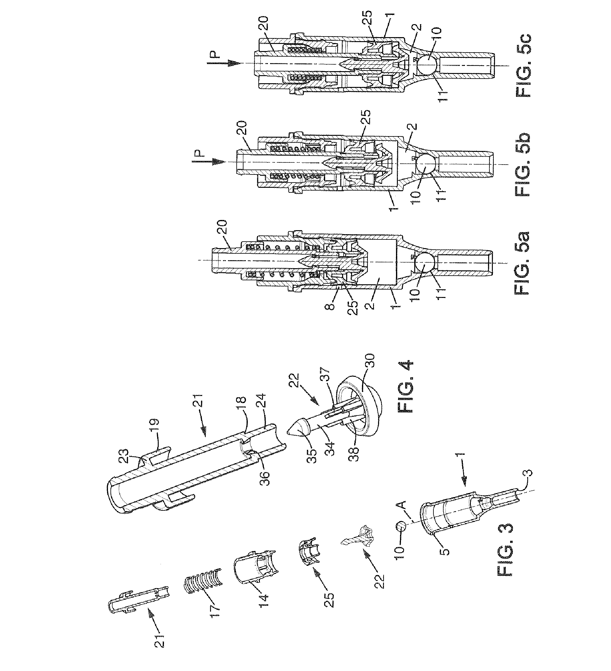
[0010]Therefore, the ball-and-socket joint allows easier assembly and manufacture of the insert and of the actuation tube. In addition, it makes it possible to obtain a centering and a self-alignment between the insert and the actuation tube and between the piston and the body so as to obtain a uniformity in the contacts between the annular surfaces of the base and of the piston and a better distribution of the pressure of the piston inside the body. This arrangement then makes it possible to improve the sealing of the piston and of the discharge valve and to limit the wear thereof.
[0025]the pump comprises an annular extender associated with the second end of the body and suitable for guiding the actuation tube in translation along the central axis, and an elastic member suitable for returning the stem to the far position, said elastic member being placed between the extender and the actuation tube: this arrangement makes it possible in particular to improve the compactness of the pump and prevent any risk of contamination of the fluid product by contact with the elastic member.

Problems solved by technology

Such a pump poses problems in terms of fabrication because it requires a precise relative positioning of the insert and of the actuation tube and requires the insert and the actuation tube to be manufactured with reduced tolerances.
In addition, the known pump has piston sealing and wear problems.
As a result, the piston cannot exert a distributed pressure on the inside of the body which adversely affects the sealing and increases the risks of premature wear of the piston.
The result of this is a lack of sealing of the discharge valve and a risk of wear of the piston surfaces.

Method used


Image

  • Pump For Delivering A Fluid Product
  • Pump For Delivering A Fluid Product
  • Pump For Delivering A Fluid Product

Examples


first embodiment

[0076]In the first embodiment shown in FIGS. 1 to 5, the passageways are formed between the fins 37, on the one hand, and between the head 35 and discontinuities arranged in the rim 36, on the other hand.

[0077]As a variant not shown, it is however possible to provide that the rim 36 is continuous and comprises no discontinuity. The passageways for the fluid product may then be created by a space formed between the rod 34 and the rim 36, for example because of a difference between the external diameter of the rod 34 and the internal diameter of the rim 36.

second embodiment

[0078]In the second embodiment shown in FIGS. 6 to 10, the head 35 rests on the rim 36 which may be continuous. Flats 39 may then be arranged on the head 35 and extend along the rod 34 to form the passageways.

[0079]As a variant not shown, the rim 36 may have discontinuities.

[0080]The combination of the snap-fitting of the head 35, the axial clearance Ja and the transverse clearance Jt forms a connection equivalent to a ball-and-socket connection and makes it possible to arrange, in addition to the ball-and-socket joint, an axial range of movement between the insert 22 and the actuation tube 21.

[0081]However, in other embodiments not shown, it is possible to provide for the contact surfaces of the head 35 and of the rim 36 to be curved or inclined relative to a transverse plane. In addition, the embodiment of the ball-and-socket joint is not limited to the embodiment described above. The head 35 of the rod 34 may for example be spherical and placed in a matching housing formed on the...


PUM


Abstract

A pump comprising a tubular body delimiting internally a metering chamber and comprising an inlet orifice, an inlet valve, a stem mounted so as to be able to move inside the body and comprising an actuation tube delimiting an outlet duct, an insert assembled to the actuation tube and comprising a base placed inside the metering chamber and facing the inlet orifice, and a discharge orifice, an annular piston mounted so as to slide inside the body and on the stem, the piston and the base comprising annular surfaces suitable for forming a discharge valve, a ball-and-socket joint being arranged between the insert and the actuation tube.

Description

CROSS-REFERENCE TO RELATED APPLICATIONS[0001]The present application claims priority of French patent application No. 06 10044 filed on Nov. 16, 2006, the content of which is incorporated herein by reference.FIELD OF THE INVENTION[0002]The invention relates to a pump for delivering a fluid product.[0003]More particularly, the invention relates to a pump for delivering a fluid product comprising a tubular body extending along a central axis between a first end and a second end, delimiting internally a metering chamber and comprising an inlet orifice for the fluid product in the metering chamber in the vicinity of said first end, an inlet valve suitable for selectively closing off the inlet orifice, a stem mounted so as to be able to move axially inside the body between a far position and a near position relative to the inlet orifice, said stem being returned elastically to the far position, said stem comprising an elongated axial actuation tube delimiting an outlet duct, an elongated...

Claims


Application Information

Patent Timeline
IPC IPC(8): F04B49/00
CPCB05B11/3023B05B11/1023
Inventor ROY, CHRISTOPHELANGLOIS, YOHANN
Owner ALBEA LE TREPORT
Learn More