Short-circuit device having pyrotechnic trigger

A technology of circuit breaker and pyrotechnics, which is applied in the direction of high-voltage air circuit breakers, circuits, electrical components, etc., can solve problems such as high mechanical costs, and achieve the effects of long service life, reliable operation, and reliable switching

Inactive Publication Date: 2010-12-22
SIEMENS AG
View PDF10 Cites 5 Cited by
  • Summary
  • Abstract
  • Description
  • Claims
  • Application Information

AI Technical Summary

Problems solved by technology

But the two-stage line leads to high mechanical costs
In addition, due to the air gaps to be observed and the parallel configuration of the mechanical and pyrotechnic switches, great space requirements arise

Method used


Image

  • Short-circuit device having pyrotechnic trigger
  • Short-circuit device having pyrotechnic trigger
  • Short-circuit device having pyrotechnic trigger

Examples


Embodiment Construction

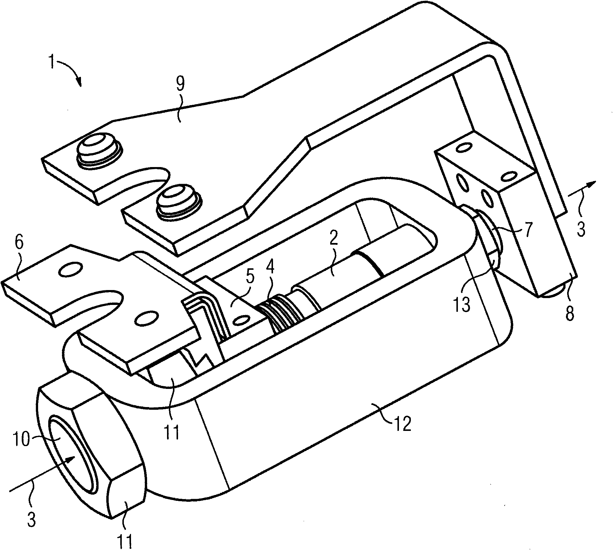
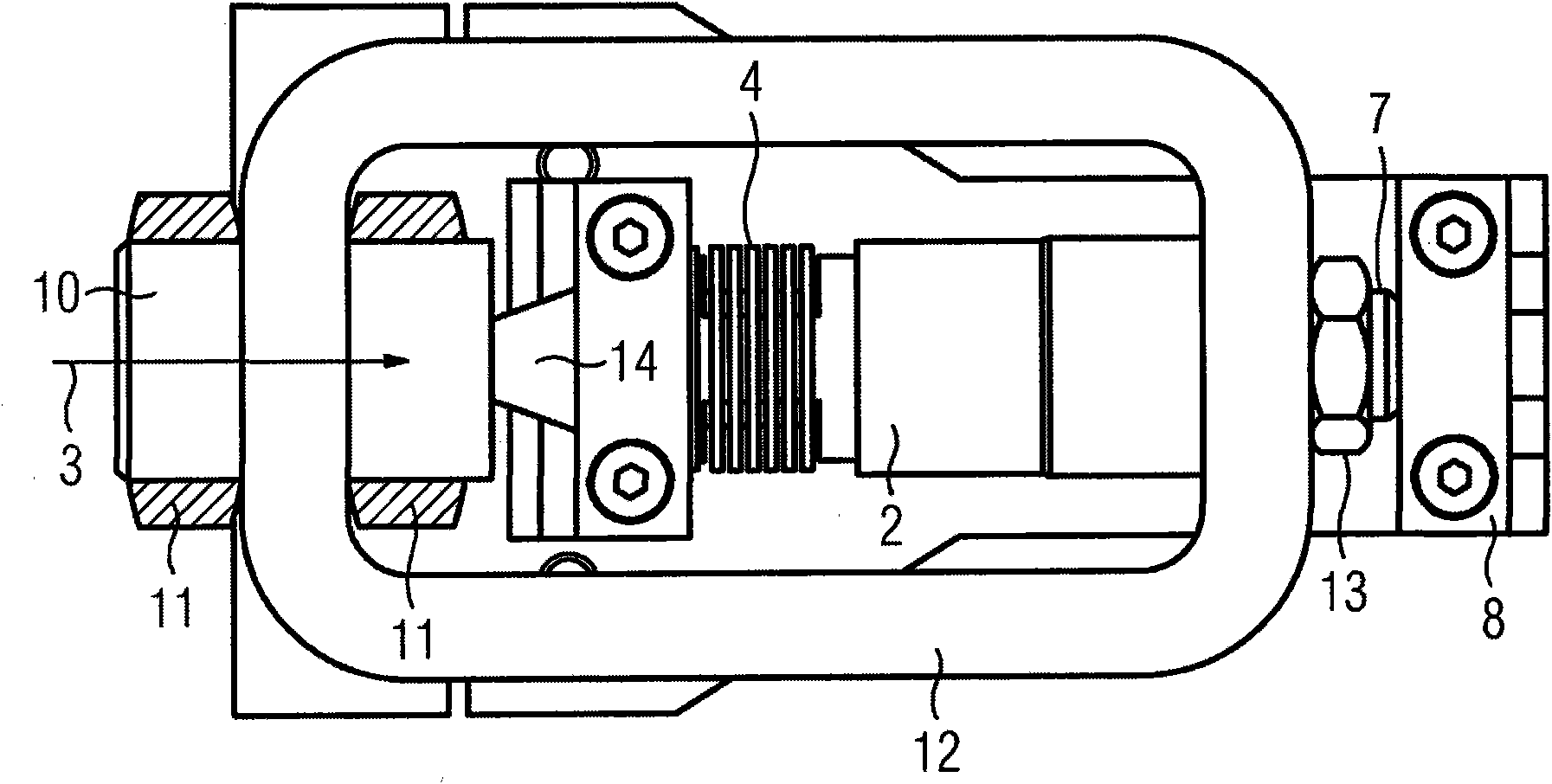
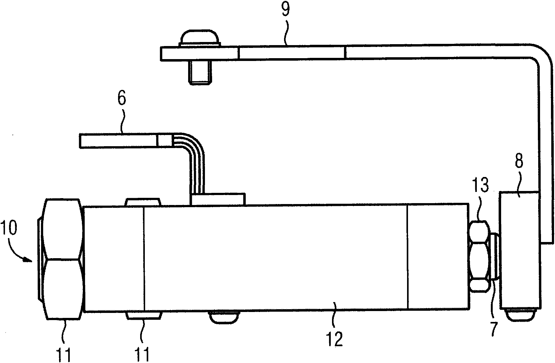
[0021] figure 1 A perspective view showing an embodiment of the short circuiter 1 of the present invention. The illustrated short circuiter 1 has a vacuum switching tube 2, in which a vacuum switching chamber not shown in the figure is designed to be evacuated. In the vacuum switching chamber of the vacuum switching tube 2 , a fixed contact (not shown) and a moving contact, which are fixedly connected to the vacuum switching tube 2 , face each other in the longitudinal direction 3 . The moving contact is guided in longitudinal 3 movement so that by the incoming drive movement, in this case a stroke movement, the moving contact is pressed against the fixed contact so that current can flow through the vacuum interrupter 2.

[0022] In order to movably fix the moving contact while maintaining the vacuum inside the vacuum switch chamber, a metal bellows box 4 is provided. The metal bellows box 4 is fixed vacuum-tight on the moving contact pin which carries said moving contact o...


PUM


Abstract

In order to provide a short-circuit device (1) for the electrical bypass of an electric module having a contact arrangement, which is disposed in a switching chamber, and which has an open circuit-breaker setting, in which a current flow via the contact arrangement is interrupted, and a contact setting, in which a current flow via the contact arrangement is made possible, and having a pyrotechnic drive (10) for transferring the contact arrangement from its circuit breaker setting into its contact setting, using which a cost-effective, rapid bypass or short-circuit is made possible, wherein a large current carrying capacity is provided simultaneously, it is proposed that the switching chamber is a vacuum switching chamber (2), in which a vacuum prevails.

Description

technical field [0001] The invention relates to a short-circuit device for conductively bridging electrical components, comprising a contact device arranged in a switching chamber, the contact device having an open disconnection position and a contact position, in which the current is interrupted by the contact device , current can flow through the contact device when in the contact position; and a pyrotechnic actuator is included for converting the contact device from its open position to its contact position. [0002] The invention also relates to a device for current commutation in the field of electric energy transmission and distribution, comprising a number of high-power semiconductor components connected to each other by electrical connection means to form a series circuit, wherein for each high-power semiconductor component A short-circuit device across the respective high-power semiconductor components. Background technique [0003] Such a crowbar is known from DE1...

Claims


Application Information

Patent Timeline
Patent Type & Authority Applications(China)
IPC IPC(8): H01H33/66H01H39/00
CPCH01H33/666H01H39/004
Inventor 詹斯·伯格乔尔格·多恩托马斯·库贝尔罗曼·伦兹安德烈亚斯·施特尔泽安德烈亚斯·曾克纳
Owner SIEMENS AG
Why Eureka
Try Eureka