

Electrical drive machine having stator and rotor
A technology for driving motors and rotors, applied to electrical components, electromechanical devices, DC commutators, etc., can solve problems such as reducing service life and achieve the effect of prolonging service life
- Summary
- Abstract
- Description
- Claims
- Application Information
AI Technical Summary
Problems solved by technology
Method used
Image

Examples
Embodiment Construction
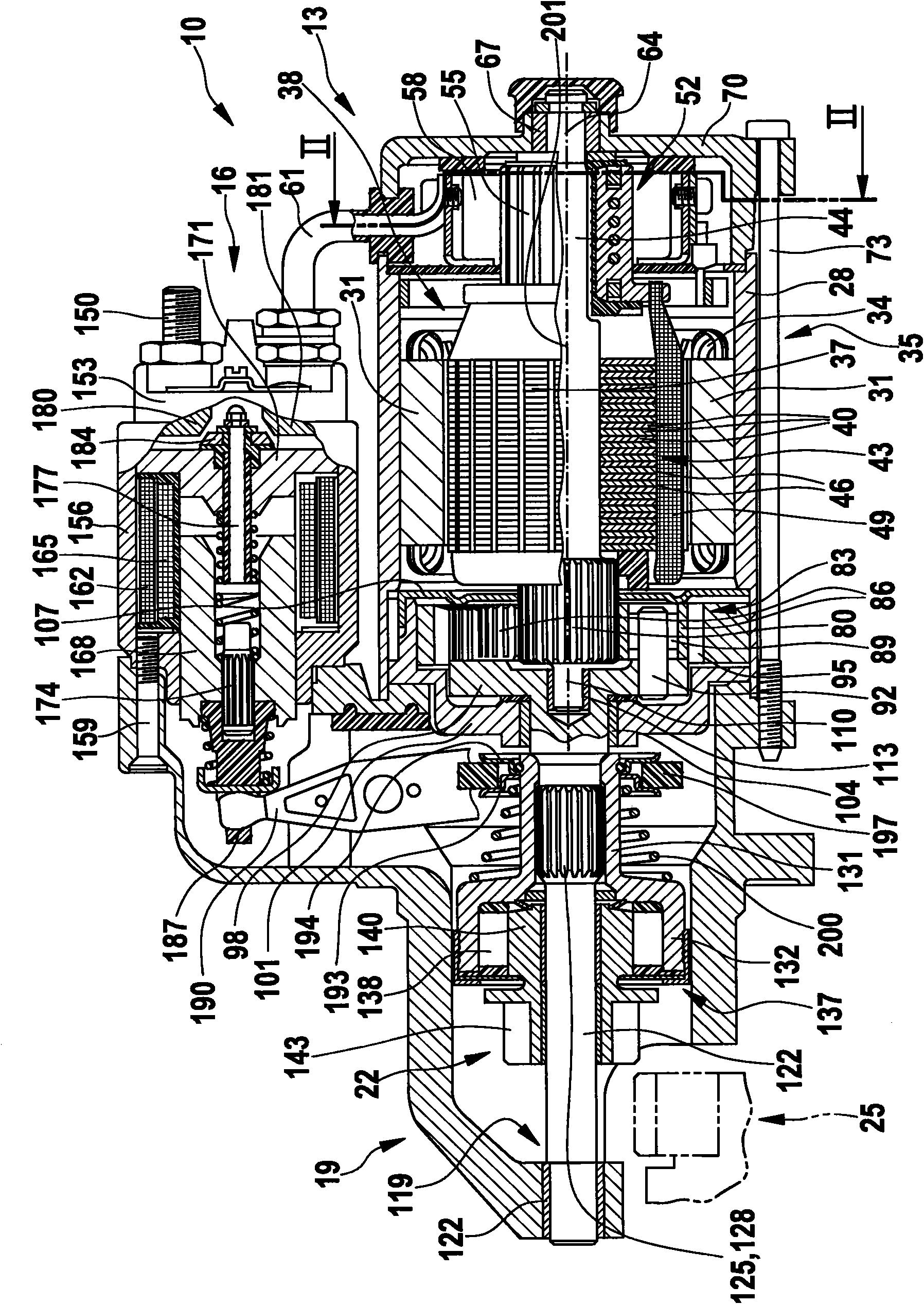
[0010] figure 1 The starting device is shown in longitudinal section. exist figure 1 The starting device 10 is shown in . The starter device 10 has, for example, a starter motor 13 and a switching relay 16 . Both starter motor 13 and switching relay 16 are fastened in a common drive end bearing housing 19 . The starter motor 13 is functionally available to drive the starter pinion 22 when the starter pinion 22 meshes in a ring gear 25 of the internal combustion engine (not shown here).
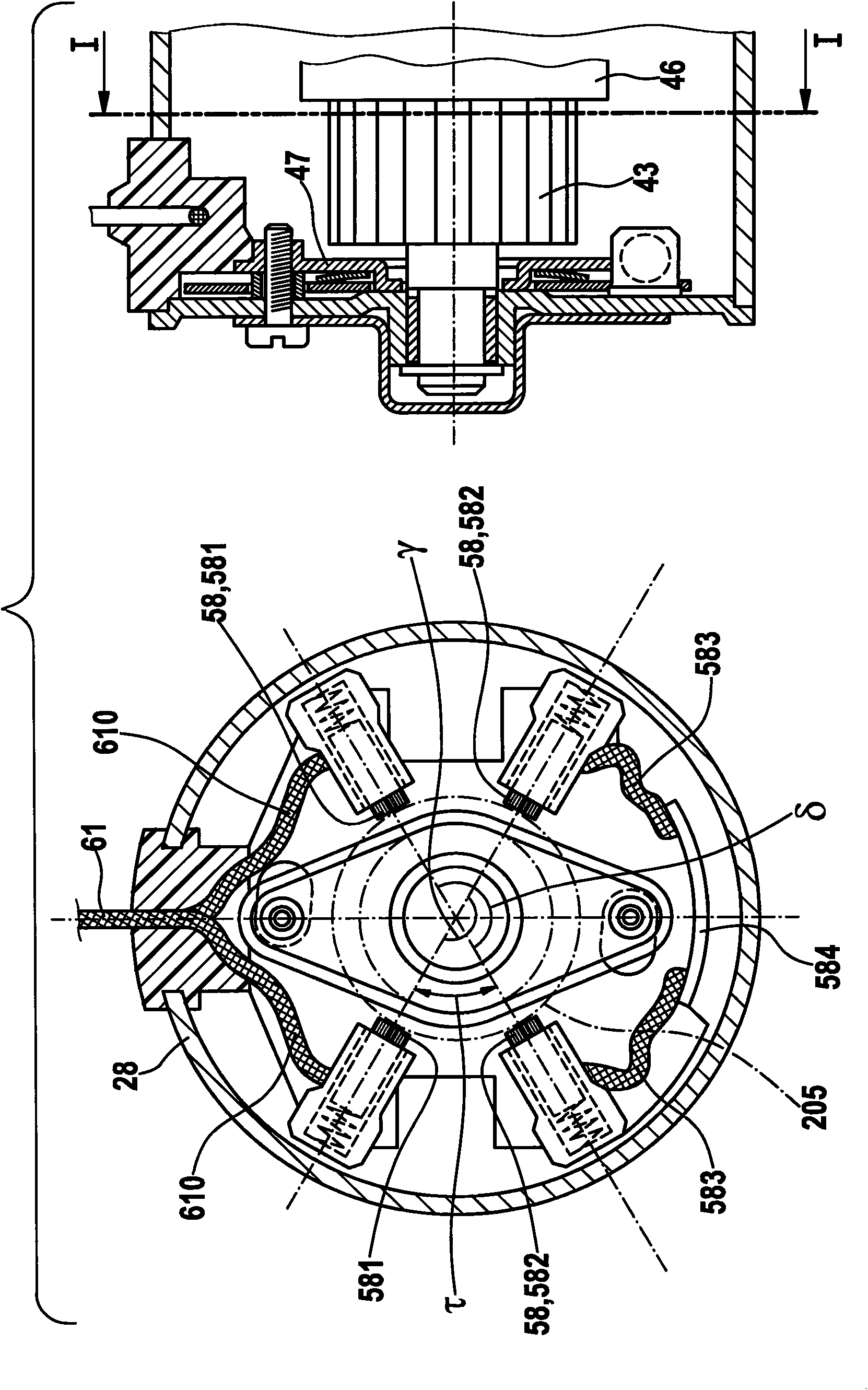
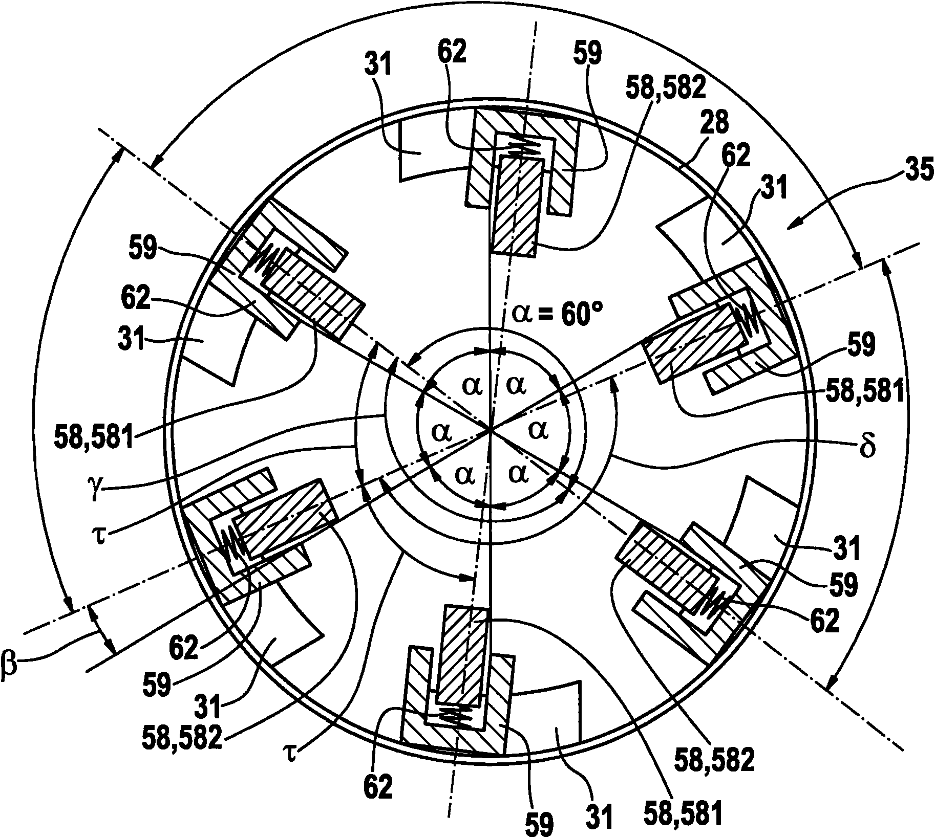
[0011] The starter motor 13 as a drive motor of the starter has a pole tube 28 as a housing, which has a plurality of pole shoes 31 each wound by a field winding 34 on its inner periphery. The pole shoe 31 in turn surrounds an armature 37 , ie a rotor 38 , which has an armature core 43 consisting of laminations 40 and an armature or rotor winding 49 arranged in slots 46 . The armature core 43 is pressed against the drive shaft 44 . Also mounted on the end of the drive shaft 44 remote fro...
PUM
 Abstract
Description
Claims
Application Information