
Grinding device of shallow trench isolation structure and method therefor

A technology of isolation structure and grinding device, applied in grinding device, grinding automatic control device, grinding machine tool, etc., can solve the problem of not being able to stop grinding at the interface

Active Publication Date: 2010-12-29
CSMC TECH FAB2 CO LTD
View PDF5 Cites 9 Cited by
  • Summary
  • Abstract
  • Description
  • Claims
  • Application Information

AI Technical Summary

Problems solved by technology

From the actual grinding point of view, the grinding cannot be accurately stopped at the interface

Method used


Image

  • Grinding device of shallow trench isolation structure and method therefor
  • Grinding device of shallow trench isolation structure and method therefor
  • Grinding device of shallow trench isolation structure and method therefor

Examples


Embodiment Construction

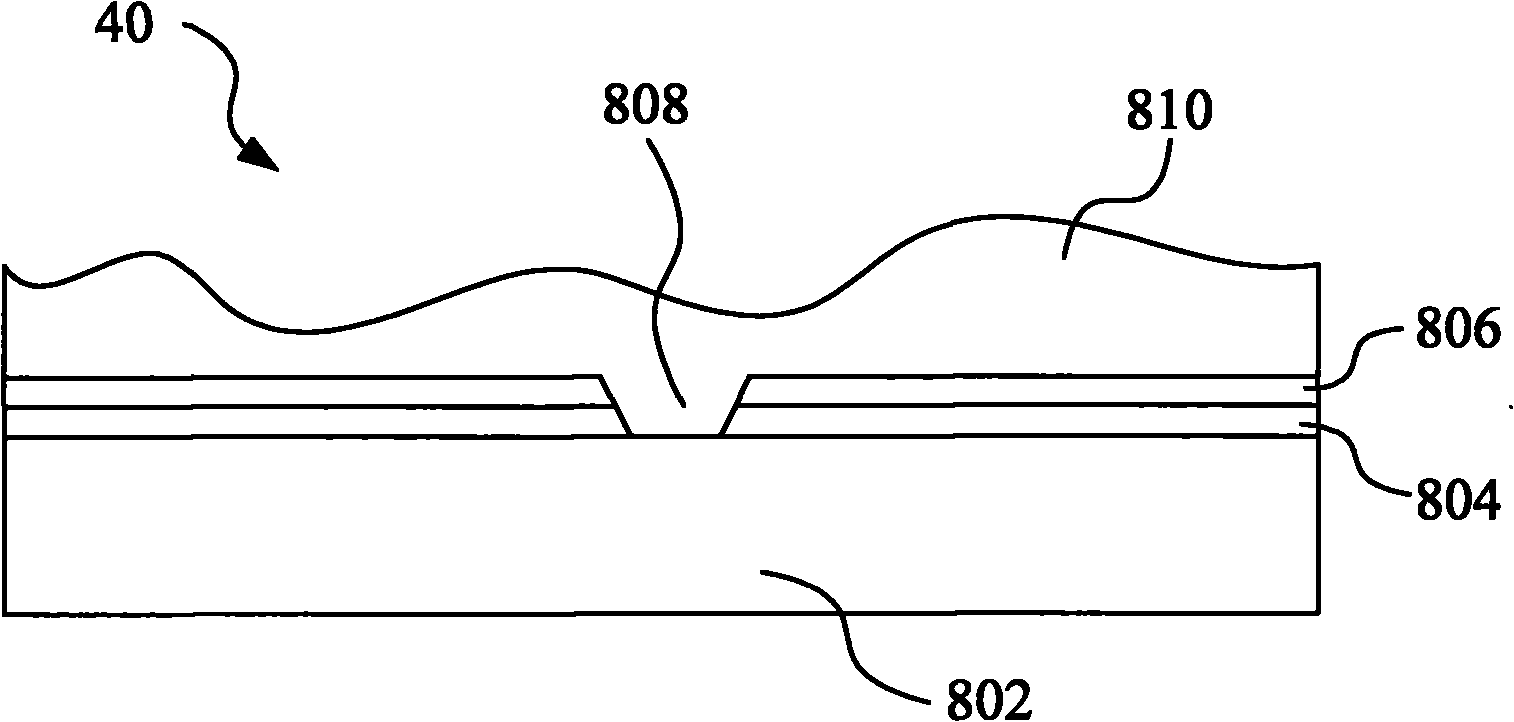
[0026] Such as figure 1 As shown, a shallow trench isolation structure formed on a wafer 40 includes a substrate 802, a first SiO formed on the substrate 802 2 layer 804, SiN layer 806, trench 808, and a second SiO formed on SiN layer 806 and within trench 808 2 Layer 810. For subsequent process requirements, in the second SiO 2 After the layer 810 is formed, it needs to be polished, and the end point of the grinding is between the SiN layer 806 and the second SiO 2 layer 810 interface.

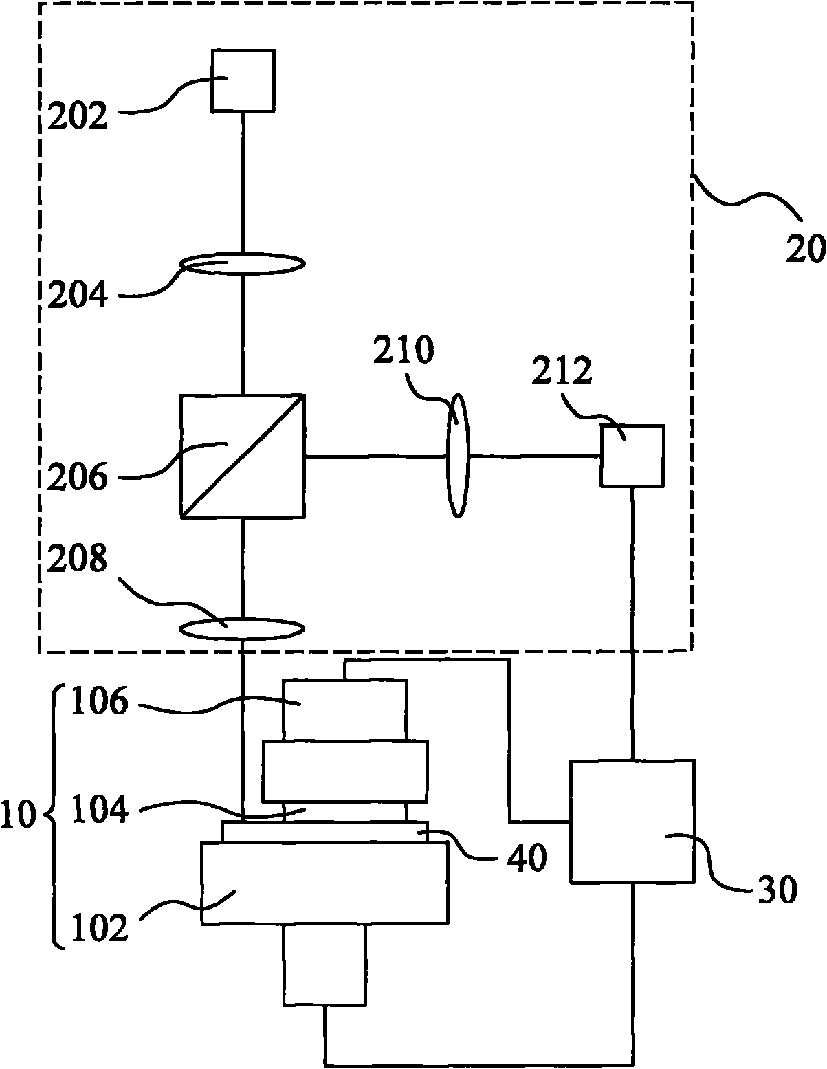
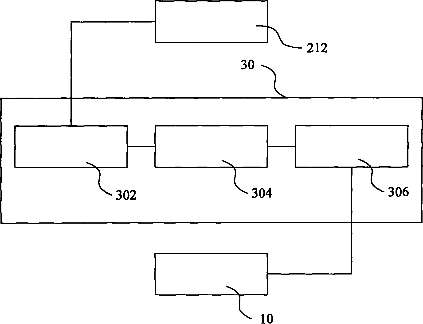
[0027] Such as figure 2 As shown, one embodiment of the grinding device for the shallow trench isolation structure of the present invention includes a grinding part 10 , a monitoring part 20 and a control part 30 . The grinding part 10 is used for grinding the shallow trench isolation structure on the wafer 40, that is, grinding the second SiO formed on the surface of the SiN layer 806 2 Layer 810. The monitoring part 20 is used to monitor the grinding surface of the wafer 40 and feed...


PUM


Abstract

The invention relates to a grinding device of a shallow trench isolation structure, comprising a grinding part, a monitoring part and a control part. The grinding part is used to grind a silicon dioxide layer on a silicon nitride layer. The monitoring part is used to project downgoing monitoring light to a grinding surface and receiving upgoing light reflected by the grinding surface so as to generate induction signals corresponding to the upgoing light. The control part is used to carry out preset comparison according to the induction signals and then determine whether the grinding surface reaches the dividing line between the silicon nitride layer and the silicon dioxide layer, and generate corresponding control signals to control grinding motion of the grinding part. The invention also provides a corresponding grinding method of the shallow trench isolation structure.

Description

【Technical field】 [0001] The invention relates to a semiconductor process, in particular to a polishing device and method for a shallow trench isolation structure in the semiconductor manufacturing process. 【Background technique】 [0002] In the semiconductor process, the isolation between the active regions of the MOS devices is mostly in the form of shallow trench isolation (Shallow Trench Isolation). [0003] The formation process of a shallow trench isolation structure includes: respectively forming a first oxide layer and a nitride layer on the surface of a substrate; etching to form a trench; depositing and forming a second oxide layer on the surface of the trench and the nitride layer; grinding The second oxide layer reaches the interface with the nitride layer. [0004] When determining the interface, there are usually methods such as measuring the resistance value, measuring the grinding thickness, measuring the remaining thickness and the motor speed to calculate ...

Claims


Application Information

Patent Timeline
IPC IPC(8): B24B37/04B24B49/04B24B49/12B24B51/00H01L21/304B24B37/00
Inventor 李健李勇曾明
Owner CSMC TECH FAB2 CO LTD
Learn More