
Die

A mold and template technology, which is applied in the field of wedge-shaped light guide plate injection molding molds, can solve the problems affecting the size uniformity and optical performance of the light guide plate, the difference in the shrinkage degree of the wedge-shaped light guide plate, and the warping deformation of the wedge-shaped light guide plate. Improve dimensional uniformity and optical performance, small dimensional error, and consistent shrinkage

Inactive Publication Date: 2010-12-29
HONG FU JIN PRECISION IND (SHENZHEN) CO LTD +1
View PDF2 Cites 7 Cited by
  • Summary
  • Abstract
  • Description
  • Claims
  • Application Information

AI Technical Summary

Problems solved by technology

Therefore, it may happen that the thick side has not been filled completely, but the thin side has begun to cool and solidify, which makes the shrinkage degree of the wedge-shaped light guide plate have a large difference, resulting in a large dimensional error, and may even cause the wedge-shaped light guide plate to warp and deform. , which seriously affects the dimensional uniformity and optical performance of the light guide plate

Method used


Image

  • Die
  • Die
  • Die

Examples


Embodiment Construction

[0013] The mold of the technical solution will be further described in detail below in conjunction with the embodiments and the accompanying drawings.

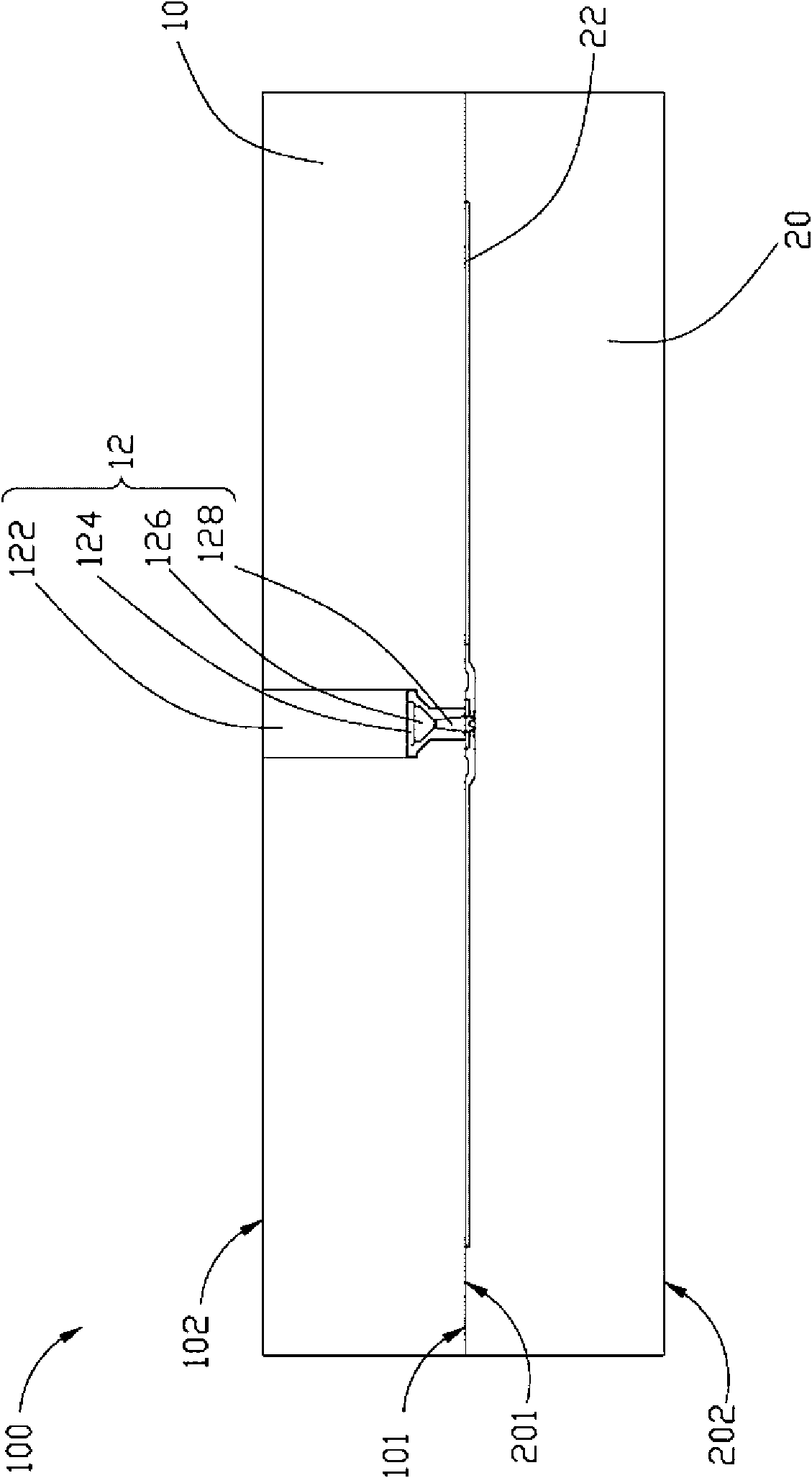
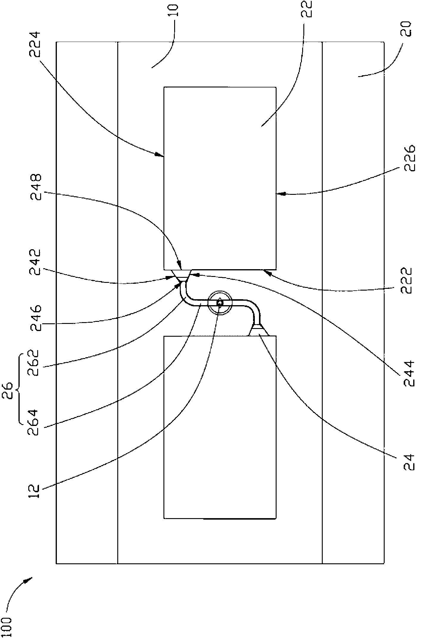
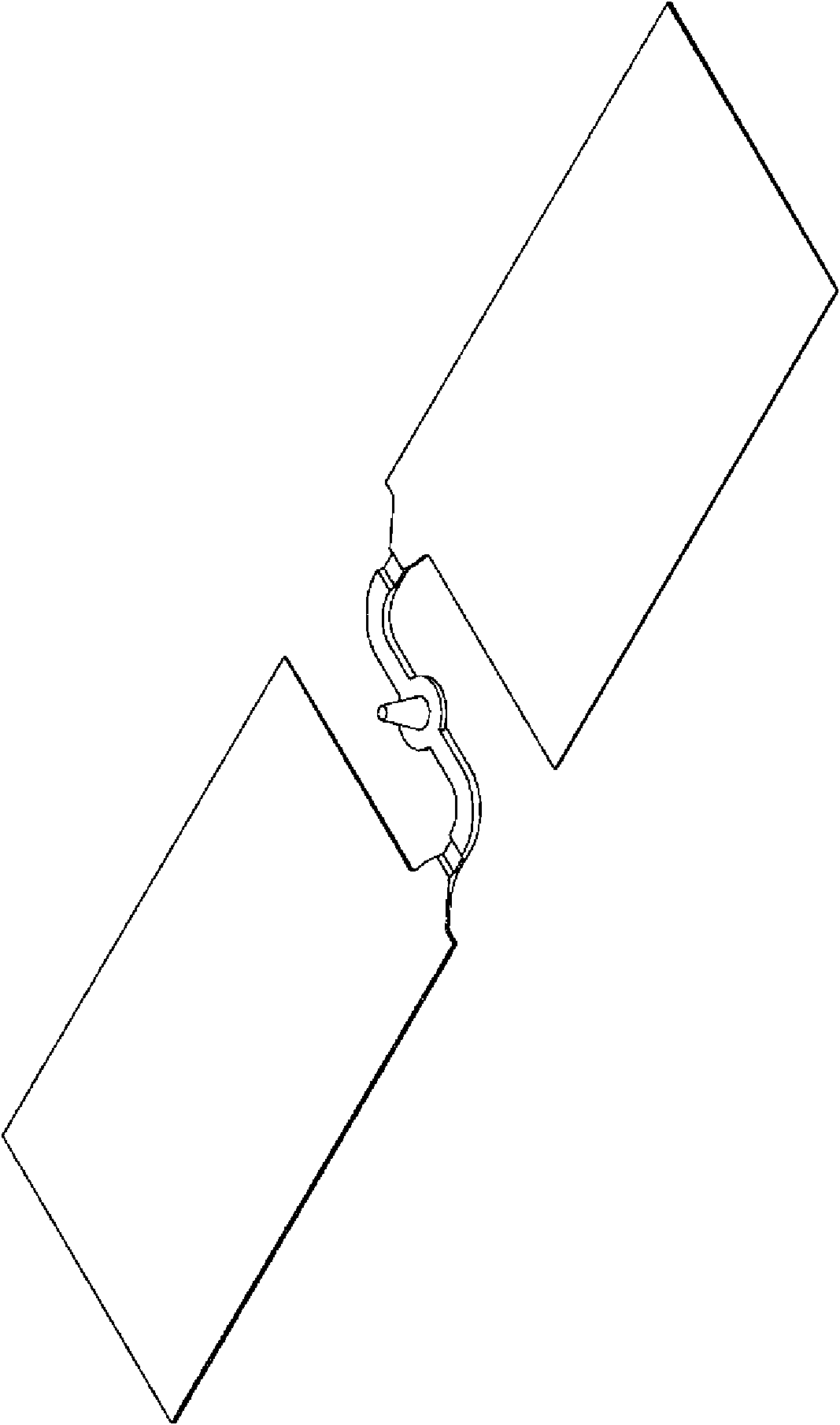
[0014] see figure 1 and figure 2 , The mold 100 provided by the embodiment of the technical solution includes a first template 10 and a second template 20 .

[0015] The first template 10 has a first surface 101 and a second surface 102 opposite to each other. The first surface 101 is opposite to the second template 20 , and the second surface 102 is away from the second template 20 . The first template 10 defines a main channel 12 inwardly from the first surface 101 . The main channel 12 runs through to the second surface 102 . The sprue 12 is used for injection molding of molten plastic.

[0016] In this embodiment, the main channel 12 includes a straight section 122 , a buffer section 124 , a constriction section 126 and an expansion section 128 connected in sequence. Wherein, the straight-line section 122 is opened ...


PUM


Abstract

The invention relates to a die, which comprises a first template and a second template, wherein the second template is provided with a surface opposite to the first template; the second template is provided, inwards from the surface, with a wedge-shaped die cavity and a sprue which is communicated with the wedge-shaped die cavity; the wedge-shaped die cavity is provided with a pouring end face connected with the sprue, and a first lateral end face and a second lateral end face which are connected to both sides of the pouring end face respectively; the depth of the first lateral end face of the wedge-shaped cavity is more than that of the second lateral end face; a distance between the sprue and the first lateral end face is less than that between the sprue and the second lateral end face; the sprue is provided with a first sidewall adjacent to the first lateral end face and a second sidewall adjacent to the second lateral end face; and an included angle between the first sidewall and the pouring end face is less than that between the second sidewall and the pouring end face.

Description

technical field [0001] The invention relates to mold technology, in particular to a wedge-shaped light guide plate injection molding mold. Background technique [0002] With the rapid development of backlight module technology, its application in liquid crystal displays, mobile phone display screens, floor tiles, billboards, etc. is becoming more and more extensive. The light guide plate is an important light transmission element in the backlight module, and the optical properties of the light guide plate directly affect the light emission effect of the backlight module. For the production and application related technologies of the light guide plate, please refer to the paper Fabrication of Ultraviolet range Light Guide Plate published by Okayama, Y et al. in Micro-Nano Mechatronics and Human Science, 2008.MHS 2008.International Symposium on 2008. [0003] Among them, the wedge-shaped light guide plate occupies an important position in the application of the light guide pl...

Claims


Application Information

Patent Timeline
Patent Type & Authority Applications(China)
IPC IPC(8): B29C45/26B29C45/27F21V8/00
CPCB29L2011/0075B29C39/24
Inventor 吴锡章
Owner HONG FU JIN PRECISION IND (SHENZHEN) CO LTD
Learn More