
Stop treatment method for ink-jet recording apparatus

A technology of inkjet recording and processing method, applied in printing and other directions, can solve the problems of reduced suction efficiency, longer stop processing time, reduced liquid flow, etc., to achieve the effect of reducing the amount of solvent

Active Publication Date: 2010-12-29
HITACHI IND EQUIP SYST CO LTD
View PDF4 Cites 8 Cited by
  • Summary
  • Abstract
  • Description
  • Claims
  • Application Information

AI Technical Summary

Problems solved by technology

However, if the suction flow path and the recovery flow path are sucked at the same time during the stop process, the flow rate of the liquid flowing through each flow path will decrease compared with the case of suction by independent pumps, and the suction efficiency will decrease.
If a solenoid valve is installed in each flow path, and by switching the solenoid valve, only one flow path is sucked with one pump, and the other flow path is sucked separately after suction, then although the required suction can be performed, but because only Suction can be performed in one flow path, and as a result, there is a problem that the stop processing time becomes longer

Method used


Image

  • Stop treatment method for ink-jet recording apparatus
  • Stop treatment method for ink-jet recording apparatus
  • Stop treatment method for ink-jet recording apparatus

Examples


Embodiment Construction

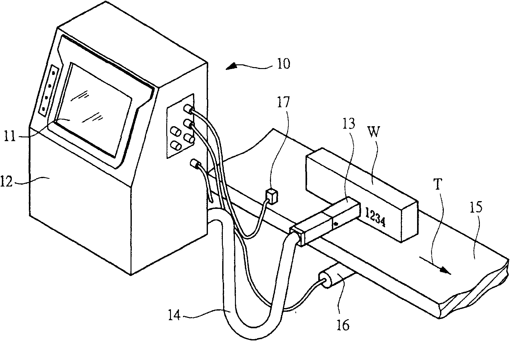
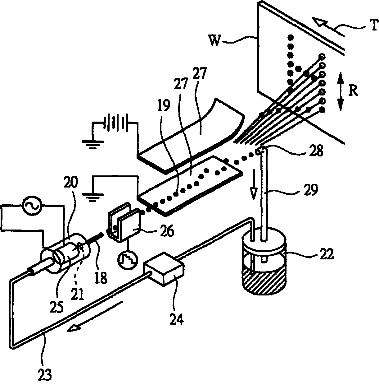
[0043] Hereinafter, embodiments of the present invention will be described in detail with reference to the drawings. Such as figure 1 As shown, the inkjet recording device 10 has a device main body 12 provided with an operation display portion 11 on the front, and a printing head 13 is connected to the device main body 12 through a conduit 14 . The inkjet recording apparatus 10, for example, as figure 1 As shown, it is installed on the production line of a factory that produces food or beverages, and the packaging of food or the like is used as the object to be printed, that is, the object to be printed W, and is used to print marks on it. The device main body 12 is disposed on the upper surface of a support table not shown so as to be operable by a user. The printing head 13 is placed close to the object W conveyed by the conveyor belt 15, and the inkjet recording device 10 performs printing on the object W on the conveyor belt 15 moving in the direction indicated by the ar...


PUM


Abstract

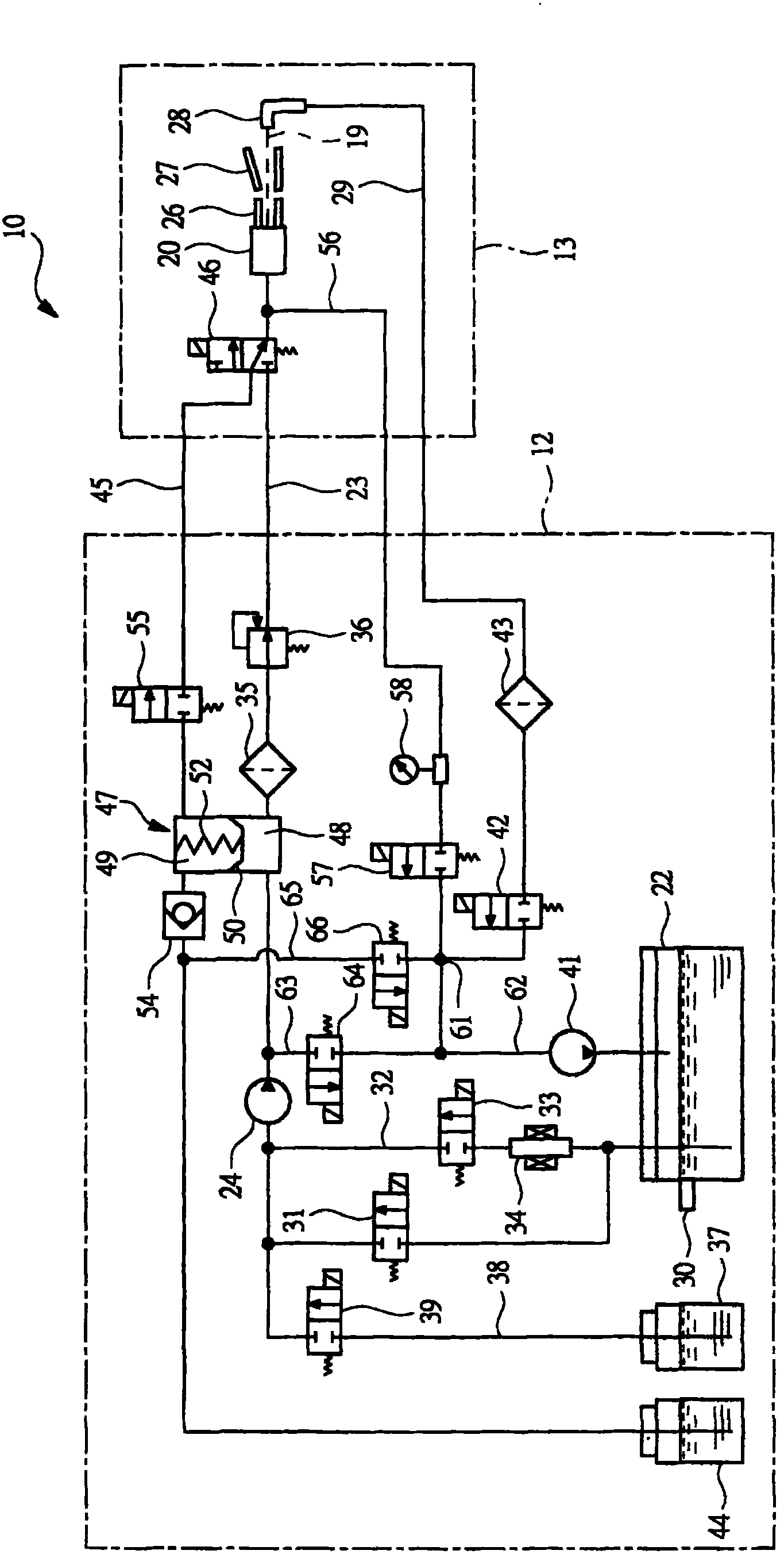
The invention provides a stop treatment method for an ink-jet recording apparatus, and aims to carry out stop treatment for the ink-jet recording apparatus through a small amount of solvent. During the process from printing state of injecting ink by a nozzle (20) to state of stopping supplying ink to the nozzle (20), solvent is supplied to the nozzle (20) from a solvent supply flow path (45), the solvent flowed through the nozzle (20) is supplied to a recovery flow path (29) to clean the recovery flow path (29), then solvent is supplied to an attraction flow path (56) from the solvent supply flow path (45) to clean the attraction flow path (56), outer gas is supplied to the attraction flow path (56) from the nozzle (20), and after the solvent is changed to air, the solvent is supplied to the attraction flow path (56) again to fine clean. By carrying out residual liquid removing for the attraction flow path (56) and residual liquid removing for the recovery flow path (29) alternatively and repeatedly, liquid in the recovery flow path (29) and the attraction flow path (56) are supplied to an ink container.

Description

technical field [0001] The present invention relates to a stop processing method of an inkjet recording device for cleaning ink remaining in a flow path when the operation of the inkjet recording device is stopped. Background technique [0002] As an inkjet recording device that uses the product conveyed by the conveying device of the production line as the object to be printed, that is, to print text or graphics on it, the object to be printed does not contact the nozzle of the printing head, and the ink (ink) flows from the nozzle A non-contact device that flies out towards the printed object. For example, in the case of printing characters on the surface of packaging materials such as corrugated cardboard boxes for packaging goods, the outer surface of the packaging material is printed by an inkjet recording device while being conveyed by a conveyor belt, or on a container containing a beverage. In the case of upper printing, printing is also performed on the outer surfa...

Claims


Application Information

Patent Timeline
IPC IPC(8): B41J2/165
Inventor 长岭俊秀宫尾明猪狩光雄小田部宽
Owner HITACHI IND EQUIP SYST CO LTD
Learn More