Conveyor apparatus of metal cutting chip

A technology for metal chips and conveyors, which is applied in the direction of metal processing machinery parts, metal processing equipment, packaging, etc., and can solve problems such as blockage of the discharge port and failure of the coil conveyor device, and achieve the effect of preventing blockage

Inactive Publication Date: 2010-12-29
TOSHIBA MASCH CO LTD
View PDF7 Cites 5 Cited by
  • Summary
  • Abstract
  • Description
  • Claims
  • Application Information

AI Technical Summary

Problems solved by technology

[0006] In the case of receiving a large amount of metal chips in the conventional coil conveyor device, cl...

Method used


Image

  • Conveyor apparatus of metal cutting chip
  • Conveyor apparatus of metal cutting chip
  • Conveyor apparatus of metal cutting chip

Examples


Embodiment Construction

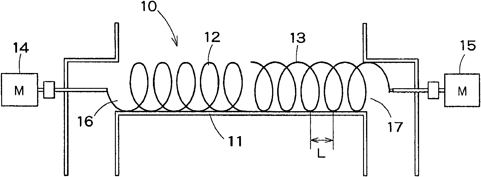
[0025] Next, preferred embodiments of the coil conveyor device of the present invention will be described in detail with reference to the drawings. figure 1 It is a schematic diagram of the coil conveyor apparatus which concerns on one Embodiment of this invention. according to figure 1 The coil conveyor device, the metal chips are discharged to the left and right discharge ports. As the coil section, a method of separating the coil on one side and the coil on the other side in which the twist directions are different from each other is adopted.

[0026] More specifically, the coil conveyor device 10 includes a receiving member 11 capable of receiving metal chips from a machine tool or the like, and coil portions 12 and 13 provided inside the receiving member 11 and driven to rotate. The coil section has one side coil 12 and the other side coil 13 whose twist directions are different from each other. One side coil 12 is driven to rotate by a motor 14 , and the other side ...


PUM


Abstract

The invention provides a coil conveyor apparatus, which can prevent blockage of a discharge port and stably discharge the metal cutting chip. The coil conveyor apparatus comprises a receiving component and a coil part arranged in the receiving component, wherein the receiving component is used for receiving the metal cutting chip from a machine tool and drives the coil part to rotate, so as to send the metal cutting chip to the outside of the receiving component. The coil conveyor apparatus is characterized in that the receiving component is provided with discharge ports at two areas, the coil part is provided with an integrated coil with twisting direction on one side being different from that of the other side, one side of the integrated coil is arranged at one side of a discharge port, while the other side thereof is arranged at the other side of the other discharge port.

Description

technical field [0001] The present invention relates to a coil conveyor device or a screw conveyor device for sending out metal chips produced by machining with a machine tool. Background technique [0002] For existing coil conveyor installations, use Figure 5 Be explained. Such as Figure 5 As shown, below the bed 3 on which the workpiece 2 is mounted on the machine tool shown by the dot-dash line, the coil conveyor device 1 is installed so as to be aligned with the moving direction of the cutting tool 4 and the like (in the Figure 5 The center is the left and right directions) correspondingly extending. This coil conveyor device 1 is a device for receiving metal chips cut off by a cutting tool and the like falling from the upper part (near the cutting tool 4 ) and sending them out of the device. The coil conveyor device 1 has : a groove-shaped receiving member 5 ; and a coil conveyor 7 provided inside the receiving member 5 and driven to rotate by a drive motor 6 . Me...

Claims


Application Information

Patent Timeline
IPC IPC(8): B65G33/10B65G33/24B65G33/26B23Q11/00
Inventor 加藤孝一
Owner TOSHIBA MASCH CO LTD
Why Eureka
Try Eureka