
Programmable logic controller (PLC)-controlled electric safety door

A safety door and control-type technology, which is applied in the direction of transportation and packaging, lifting equipment in mines, etc., can solve the problems of inability to accurately control the remote control of the cage, affect the normal operation of the cage operation system, and unfavorable mine safety production, etc., to achieve accuracy and effectiveness Duration, simple structure, smooth switching effect

Active Publication Date: 2010-12-29
CHINA SHENHUA ENERGY CO LTD +2
View PDF6 Cites 6 Cited by
  • Summary
  • Abstract
  • Description
  • Claims
  • Application Information

AI Technical Summary

Problems solved by technology

However, these types of electric safety gates have their own defects, which are not conducive to the safe production of mines.
[0004] For example, manual hand-operated safety gates require manual operation, which affects work efficiency and is prone to failure
As another example, the original design of the traffic cage safety door of Shenhua Yili Huangyuchuan Coal Mine's auxiliary shaft uses a hydraulic cylinder to drive the safety door switch. It will affect the normal operation of the cage operating system
[0005] At the same time, most of these safety doors require operators to operate, and cannot be precisely controlled or remotely controlled according to the operation of the cage, which greatly affects work efficiency during use, and the work is unstable and reliable

Method used


Image

  • Programmable logic controller (PLC)-controlled electric safety door
  • Programmable logic controller (PLC)-controlled electric safety door
  • Programmable logic controller (PLC)-controlled electric safety door

Examples


Embodiment Construction

[0030] Specific embodiments of the present invention will be described in detail below in conjunction with the accompanying drawings. It should be understood that the specific embodiments described here are only used to illustrate and explain the present invention, and are not intended to limit the present invention.

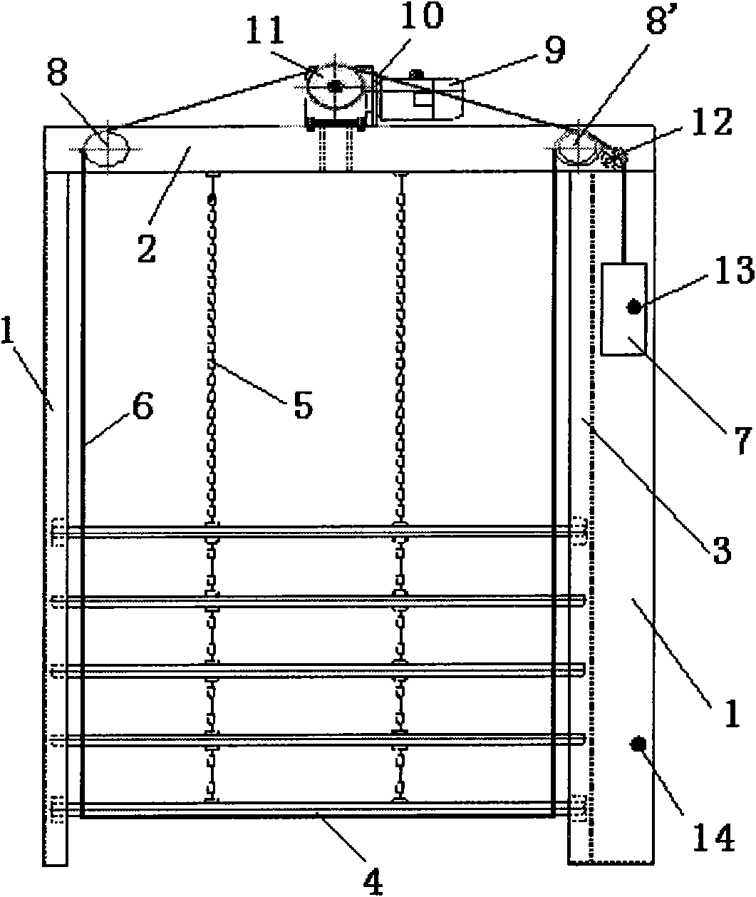
[0031] The electric safety door of the present invention is a lifting type safety door up and down. Such as figure 1 As shown, the electric safety door includes a door frame and a door body, wherein the door frame can be formed by connecting two door frame columns 1 and an upper beam 2 . Preferably, a guide groove 3 can be formed on the door frame column 1, and the door body can be slidably installed in the guide groove 3, so that the door body can be guided when the door body goes up and down, so that It is more convenient to lift up and down the door body.

[0032] Described door body 3 can adopt the door body of various forms, but preferably adopts figure...


PUM


Abstract

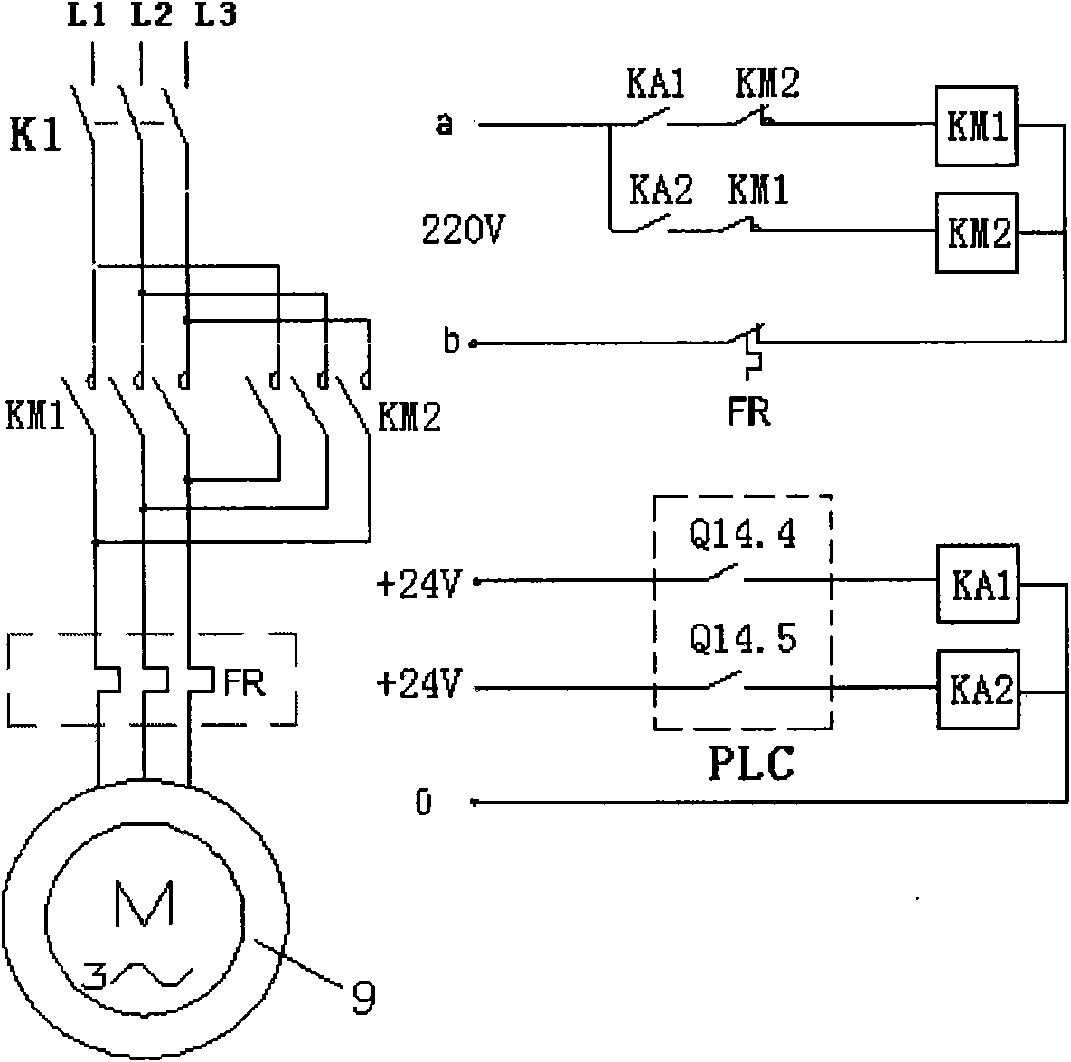
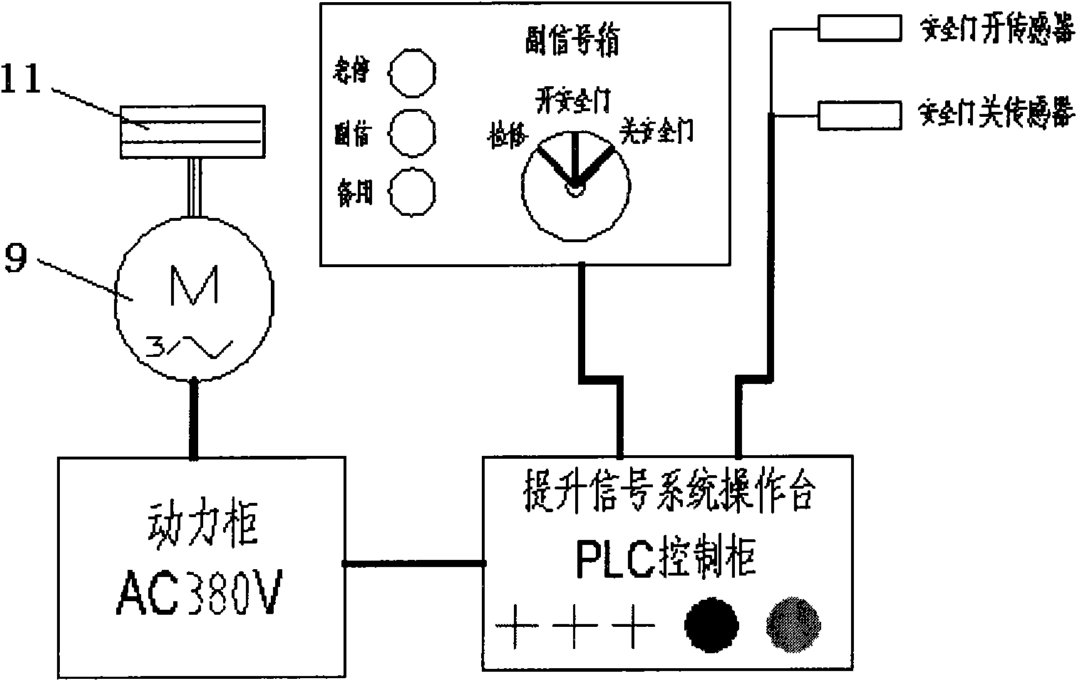
The invention relates to a programmable logic controller (PLC)-controlled electric safety door. The PLC-controlled electric safety door comprises a door frame, a door body, an electromotor (9) and a pulling rope driving wheel (11), wherein the electromotor (9) is arranged on an upper beam (2); the pulling rope driving wheel is wound with a pulling rope (6); one end of the pulling rope (6) rounds a second guide wheel (8') arranged on one side of the upper beam (2) and is connected to a counterweight block (7), while the other end rounds a first guide wheel (8) arranged on the other side, passes through one side of the door body downwards, extends to the bottom of the door body, extends to the other side of the door body along the bottom of the door body, then passes through the door body upwards, rounds the second guide wheel (8') and is fixed to the counterweight block (7); and the positive and negative rotations of the electromotor (9) are controlled by a control circuit of a programmable controller. The electric safety door is driven by the PLC-controlled electromotor, so that the electric safety door has the advantages of stable and precise switch operation, reliable working, low failure rate and effectively ensured safety of hoisting operation of coal mine vertical shafts.

Description

technical field [0001] The invention relates to an electric safety door, in particular to a PLC-controlled electric safety door. Background technique [0002] Coal mine shaft lifting cage is an important equipment for transporting mine personnel, materials and equipment, etc. Safety doors are generally installed at the entrance and exit of the lifting cage to prevent personnel, vehicles, etc. from falling into the shaft by mistake. Therefore, the safety door is an important device for coal mine shafts. [0003] At present, the opening and closing methods of the wellhead and bottom safety doors of domestic coal mine shafts include manual manual operation, cage-driven vertical lifting, hydraulic drive and pneumatic control. Among them, the safety doors of most coal mine shafts are manually operated, and some newly built mines are mostly driven by hydraulic cylinders. But these types of electric safety gates all have their own defects, which are unfavorable for the safe produ...

Claims


Application Information

Patent Timeline
IPC IPC(8): B66B17/36
Inventor 张锋高宏张长龙
Owner CHINA SHENHUA ENERGY CO LTD
Learn More