Dry connecting device

A connecting device, dry technology, used in covering/lining, building, building construction, etc., can solve the problems of unevenness, inconvenient connection operation, complex structure, etc., to achieve resistance to force and erosion, structural symmetry and stability, Stable and even force

Inactive Publication Date: 2010-12-29
安徽根源光大高深新材料有限公司
View PDF8 Cites 8 Cited by
  • Summary
  • Abstract
  • Description
  • Claims
  • Application Information

AI Technical Summary

Problems solved by technology

[0004] However, as disclosed in the Chinese patent No. 200810068058.4, the cross-section of the steel keel is "L" shaped or other overhanging, left-right asymmetrical shapes, and the bottom of the keel is connected to the preset parts with bolts or screws , the overhanging end of the keel is connected with the fastener screw. Since the bolt or screw is located between the insulation board and the wall, the connection operation is inconvenient. If the fastener and the keel are connected first and then the insulation board is installed on the fastener, the insulation board The position is difficult to place accurately, and the disturbance of the overhanging keel and fasteners is very severe, the support force received by the insulation board in all directions is not uniform, and the entire system structure is unstable; or as disclosed in the Chinese patent No. 200410008718.1, The keel can give the insulation board a relatively stable support force, but the same connection requires a keel and two fasteners with different structures. Such a structure is extremely complicated. It is also different, so the supporting force received by the insulation board in all directions is still asymmetric and uneven, and the insulation structure is still unstable; decorative effect

Method used


Image

  • Dry connecting device
  • Dry connecting device
  • Dry connecting device

Examples


Embodiment Construction

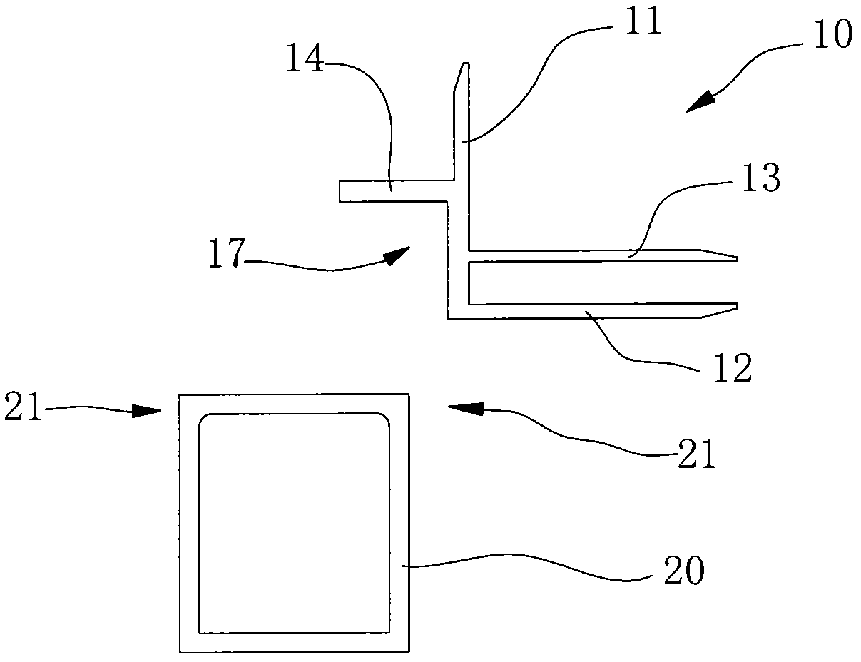
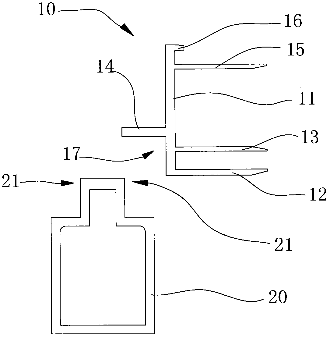
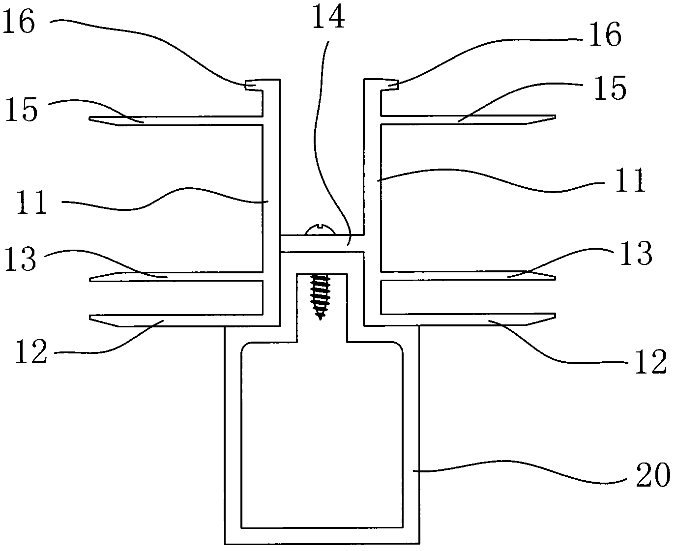
[0014] Such as figure 1 , 2 , 3, 7, and 8 show a dry connection device for thermal insulation boards, including a keel 20 and a fastener 10, the keel 20 is fixedly connected to the wall through a preset part 50, and the keel 20 is vertically positioned on the wall. And / or arranged in the horizontal direction, preferably arranged in the vertical and horizontal directions, the fastener 10 is inserted at the end of the insulation board, and then the fastener 10 is fixed to the keel 20, and the board seam is filled with filler 41 and sealant 42 filling, so that the connection between the insulation board and the wall is realized. The keel 20 of the present invention is provided with an angular portion 21 where two board surfaces intersect. The angular portion 21 includes a board surface parallel to the wall surface. The outer end surface of the fastener 10 is parallel to the wall surface, and the outer end surface forms an angled portion 21 with the adjacent plate surface near t...


PUM


Abstract

The invention relates to a connecting piece for installing an insulation board onto a wall by a dry hanging method. The connecting piece comprises a keel which is connected with the wall and a buckle piece which is connected with the insulation board, wherein an angular part of which two boards are crossed is formed on the keel and comprises one board which is parallel to the wall face; the board is positioned on the end part of the keel, which is farthest from the wall face; and an angular area which is in fit with and fixedly connected with the angular part on the keel is formed on the buckle piece. A stepped part is formed by an angular structure of the buckle piece and the keel in the scheme, therefore the installed insulation board is subjected to the support force of the stepped structure in all directions, the support structure has a large thrust surface and is symmetrical and stable, and the insulation board is subjected to the uniform and symmetrical support force in all directions. The connecting device has a simple structure and is convenient to process and use; the installed insulation board and connecting pieces are stressed stably and uniformly, have better stability, and can better resist acting force and corrosion from the outside; and durability is improved and heat insulation and decoration effects are correspondingly improved.

Description

technical field [0001] The invention relates to a thermal insulation board, in particular to a connecting piece for installing a thermal insulation board on a wall by a dry hanging method. Background technique [0002] With the needs of building insulation, energy saving and decoration, the use of insulation boards (usually integrated boards for insulation and decoration) has become very common. The installation of the insulation board mainly includes dry hanging connection and wet connection. Among them, the dry-hanging connection is widely used because it has low requirements on wall flatness and environmental conditions, and the installation process is easy to control. [0003] The main step of the dry-hanging connection of the insulation board is to set the preset parts on the wall first. The preset parts are pre-buried on the wall during wall construction or installed on the wall after the wall is formed. Install steel columns and / or beams along the surface of the wal...

Claims


Application Information

Patent Timeline
Patent Type & Authority Applications(China)
IPC IPC(8): E04F13/21E04F13/22E04F13/075
Inventor 周松桂
Owner 安徽根源光大高深新材料有限公司
Why Eureka
Try Eureka