
Oil cylinder lifting type isolating valve special for vacuum induction furnace

A vacuum induction furnace and isolation valve technology, applied in the direction of sliding valves, valve details, valve devices, etc., can solve unfavorable equipment production and use, inflatable sealing rubber ring material quality, high manufacturing precision requirements, machining and assembly design Calculation of unreliable dynamic seals and other issues to achieve the effect of eliminating heat radiation and heat conduction, simple and reliable structure, and good airtightness

Inactive Publication Date: 2010-12-29
SHENYANG VACUUM TECH INST
View PDF10 Cites 2 Cited by
  • Summary
  • Abstract
  • Description
  • Claims
  • Application Information

AI Technical Summary

Problems solved by technology

Such a structure requires high machining and assembly precision, accurate design calculations, unreliable dynamic seals, or high requirements on the material quality and manufacturing accuracy of the inflatable sealing rubber ring, which is not conducive to the production and use of equipment.

Method used


Image

  • Oil cylinder lifting type isolating valve special for vacuum induction furnace
  • Oil cylinder lifting type isolating valve special for vacuum induction furnace
  • Oil cylinder lifting type isolating valve special for vacuum induction furnace

Examples


Embodiment Construction

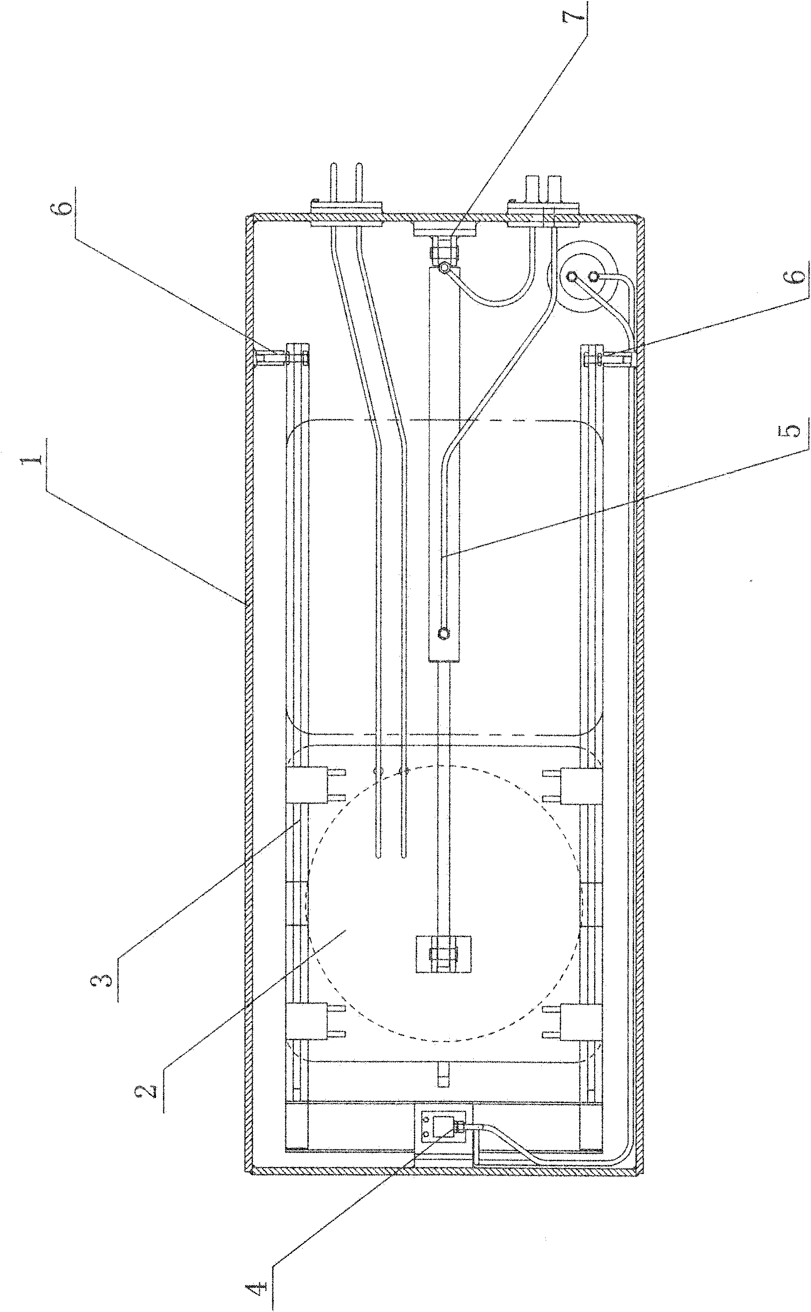
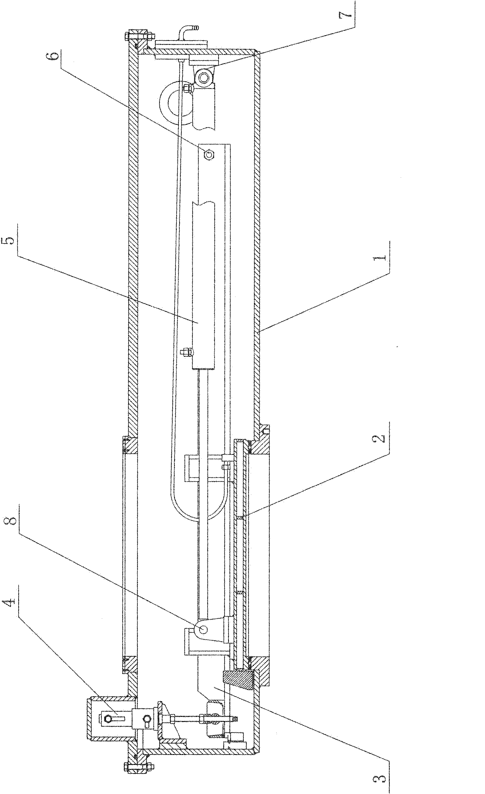
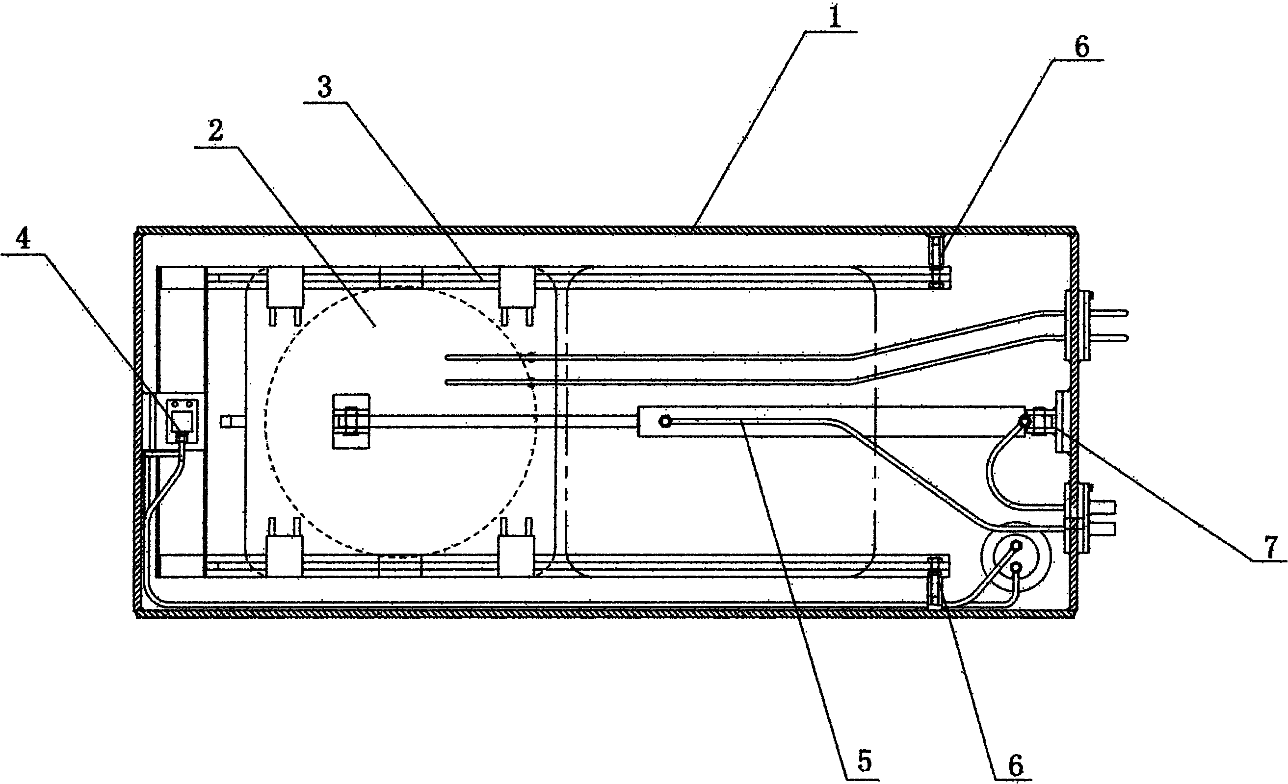
[0016] see figure 1 and figure 2 As shown, the special oil cylinder lifting isolation valve for vacuum induction furnace includes a valve body 1; a track 3, a valve plate 2, a lifting mechanism 4 and a push-pull mechanism 5 are arranged in the valve body 1; the valve plate 2 and the track 3 slidingly connected; one end of the lifting mechanism 4 is fixedly connected to the valve body 1, and the other end is axially connected to one end of the track 3; the other end of the track 3 is axially connected to the valve body 1; one end of the push-pull mechanism 5 is The hinge shaft II 8 of the push-pull mechanism is connected to the valve plate 2, and the other end is connected to the valve body 1 through the hinge shaft I 7 of the push-pull mechanism.

[0017] see figure 2 As shown, in order to simplify the structure, the lifting mechanism 4 and the push-pull mechanism 5 of the present invention respectively adopt a lifting cylinder and a push-pull cylinder in sequence. The tr...


PUM


Abstract

The invention belongs to the field of vacuum metallurgical equipment, and in particular relates to an oil cylinder lifting type isolating valve special for a vacuum induction furnace, which is applied between a main chamber and a feeding cabin or temperature measurement cabin of the vacuum induction furnace for isolating or communicating two chamber parts. The isolating valve comprises a valve body (1), wherein a track (3), a valve plate (2), a lifting mechanism (4) and a push and pull mechanism (5) are arranged in the valve body (1); the valve plate (2) is slidably connected with the track (3); one end of the lifting mechanism (4) is fixedly connected with the valve body (1), while the other end is connected with one end of the track (3) through a shaft; the other end of the track (3) is connected with the valve body (1) through the shaft; and one end of the push and pull mechanism (5) is fixedly connected with the valve plate (2), while the other end is connected with the valve body (1) through a shaft. The isolating valve has the characteristics of high sealing property, heat insulation, long service life and the like.

Description

technical field [0001] The invention belongs to the field of vacuum metallurgical equipment, and in particular relates to a special oil cylinder lifting isolation valve for a vacuum induction furnace that is applied between a main chamber of a vacuum induction furnace and a feeding bin or a temperature measuring bin to isolate or connect the two chambers. Background technique [0002] Large-scale vacuum induction furnaces are currently the smelting equipment for smelting high alloys, and the development of the material industry requires the purity of the smelted alloys to be higher and higher. In addition to requiring low impurity content, it also requires less gas content. [0003] The structure type of the isolation valve currently used in China between the main chamber of the vacuum induction furnace and the feeding bin or the temperature measuring bin is mainly that the cylinder rod of the cylinder outside the valve body passes through the valve plate which is pushed and ...

Claims


Application Information

Patent Timeline
IPC IPC(8): F16K3/02F16K31/12F16K3/30
Inventor 孙足来杨洪帅张哲魁
Owner SHENYANG VACUUM TECH INST
Learn More