
Loop type heat pipe and manufacturing method thereof

A manufacturing method and circuit technology, applied in the field of heat pipes, can solve problems such as inability to replenish liquid working fluids

Inactive Publication Date: 2010-12-29
YOUNG GREEN ENERGY
View PDF3 Cites 6 Cited by
  • Summary
  • Abstract
  • Description
  • Claims
  • Application Information

AI Technical Summary

Problems solved by technology

However, since the denser capillary structure will firmly adsorb the liquid working fluid, it is impossible to replenish the liquid working fluid to the evaporation end

Method used


Image

  • Loop type heat pipe and manufacturing method thereof
  • Loop type heat pipe and manufacturing method thereof
  • Loop type heat pipe and manufacturing method thereof

Examples


Embodiment Construction

[0036] The above and other technical content, features and effects of the present invention will be clearly presented in the following detailed description of preferred embodiments with reference to the drawings. The directional terms mentioned in the following embodiments, such as "upper", "lower", "front", "rear", "left", "right", etc., are only referring to the directions of the attached drawings. Accordingly, the directional terms are used to illustrate and not to limit the invention.

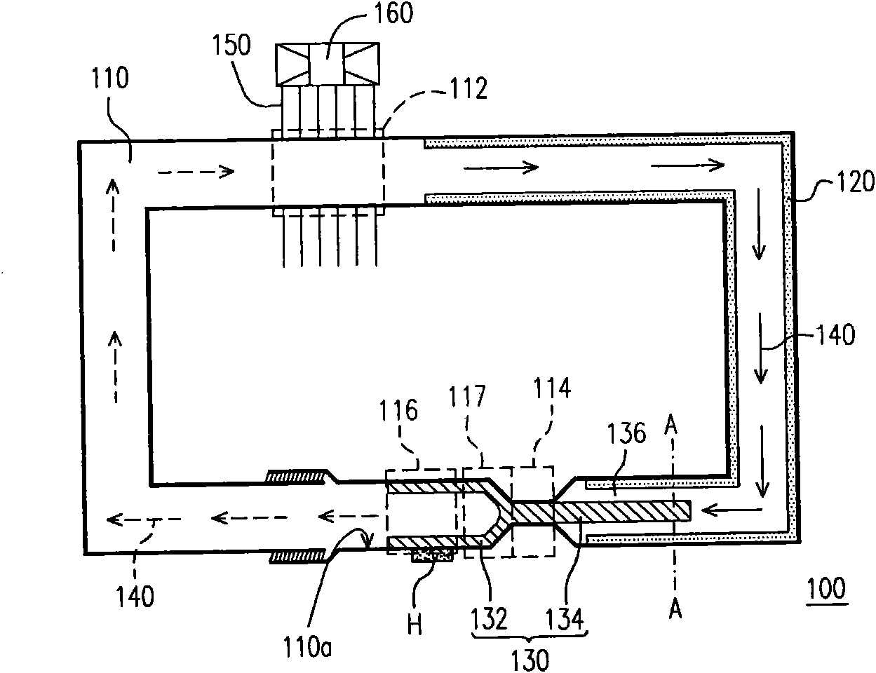
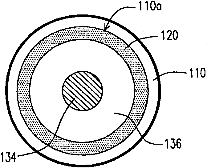
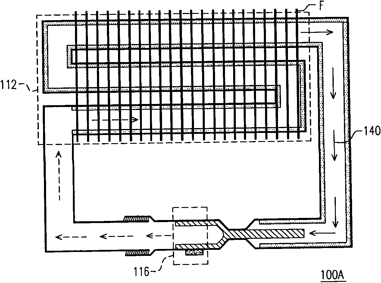
[0037] figure 1 is a schematic diagram of a loop heat pipe according to an embodiment of the present invention, and figure 2 yes figure 1 The cross-sectional view of the loop heat pipe along line A-A. Please refer to figure 1 and figure 2 , in this embodiment, the loop heat pipe 100 is suitable for dissipating heat from the heat source H. The loop heat pipe 100 includes a conduit 110 , a first capillary structure 120 , a second capillary structure 130 and a working fluid 140 dispose...


PUM


Abstract

The invention relates to a loop type heat pipe which is suitable for radiating heat of a heat source. The loop type heat pipe comprises a conduit, a first capillary structure, a second capillary structure and a working fluid arranged in the conduit, wherein the conduit is provided with a condensation section, a barrier section and an evaporation section, the evaporation section is suitable for touching the heat source in a heat conduction mode, and the barrier section is adjacent to the evaporation section; the first capillary structure is arranged on the inner surface of the conduit and between the condensation section and the barrier section; the second capillary structure is provided with a first part and a second part connected with the first part, and the first part is arranged on the inner surface of the conduit and extends to the barrier section from the evaporation section; the second part passes through the barrier section and extends towards the condensation section from the barrier section; and a gap is preserved between the first capillary structure and the second part of the second capillary structure and limits a compensated chamber.

Description

technical field [0001] The present invention relates to a heat pipe (Heat Pipe), specifically, a loop heat pipe (LoopHeat Pipe). Background technique [0002] The working principle of the heat pipe is to use the evaporation and condensation of the working fluid to transfer heat. First, the liquid working fluid evaporates into a gas by absorbing the heat emitted by the heating element adjacent to the evaporator of the heat pipe. When the gaseous working fluid is subjected to a slight pressure difference, it will flow to the condenser of the heat pipe, where it will condense into a liquid and release heat. The liquid working fluid condensed at the condensing end can be transported back to the evaporating end through the capillary structure on the inner wall of the cooked tube. Therefore, the heat pipe can be applied to heat dissipation of heat generating components. Patents related to heat pipes are, for example, US Patent No. 20080078530, and ROC Patent Nos. I248781 and 59...

Claims


Application Information

Patent Timeline
Patent Type & Authority Applications(China)
IPC IPC(8): F28D15/04
Inventor 王正
Owner YOUNG GREEN ENERGY
Learn More