Optical fiber common point target used in station-moving test process of electronic theodolite
A technology of electronic theodolite and testing process, applied in theodolite, optical device, instrument, etc., can solve the problems of large measurement error and difficult aiming of electronic theodolite, and achieve the effect of small measurement error and reduced aiming difficulty
- Summary
- Abstract
- Description
- Claims
- Application Information
AI Technical Summary
Problems solved by technology
Method used
Image
Examples
specific Embodiment approach 1
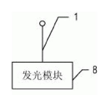
[0009] Specific implementation mode 1. Combination figure 2 Illustrate this specific embodiment, the optical fiber common point target used in the test process of electronic theodolite moving station, it comprises light-emitting module 8, is characterized in that it also comprises the optical fiber 1 that one end is sphere, and the end of the optical fiber 1 that said one end is sphere Contact with the light output end of the light emitting module 8 .
[0010] In this embodiment, the sphere on the optical fiber 1 with a sphere at one end is used as the test point of the common target of the optical fiber; when the light-emitting module 8 emits light, the sphere on the optical fiber 1 with a sphere at one end emits light at the same time, and the electronic theodolite can aim at the common target of the optical fiber in all directions. spherical luminous end.
specific Embodiment approach 2
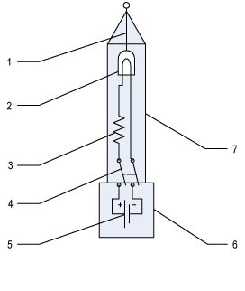
[0011] Specific embodiment two, combine image 3 Describe this specific embodiment, this specific embodiment and the optical fiber public point target described in the specific embodiment 1 are used in the electronic theodolite moving station test process, the light-emitting module 8 includes a light-emitting diode 2, a resistor 3, a switch 4 and a power supply 5 , the anode of the power supply 5 is connected to the static end of the switch 4, the moving end of the switch 4 is connected to one end of the resistor 3, the other end of the resistor 3 is connected to one end of the light emitting diode 2, the light emitting diode 2 Connect the other end to the negative pole of the power supply.
specific Embodiment approach 3
[0012] Specific embodiment three, combine Figure 4 Describe this specific embodiment, the difference between this specific embodiment and the optical fiber common point target in the electronic theodolite moving station test process described in the second specific embodiment is that it also includes a base 6 and a protective shell 7, and the protective shell 7 is set on the base; the static end of the power supply 5 and the switch is set in the base; the light-emitting diode 2, the resistor 3, the moving end of the switch 4, and the end of the optical fiber 1 with one end as a sphere are set in the protective shell 7 Middle; the top of the protective shell 7 is tapered, and the sphere of the optical fiber 1 with one end being a sphere is fixed on the top of the protective shell 7 .
PUM
 Abstract
Description
Claims
Application Information
 - R&D
- Intellectual Property
- Life Sciences
- Materials
- Tech Scout
- Unparalleled Data Quality
- Higher Quality Content
- 60% Fewer Hallucinations
Browse by: Latest US Patents, China's latest patents, Technical Efficacy Thesaurus, Application Domain, Technology Topic, Popular Technical Reports.
© 2025 PatSnap. All rights reserved.Legal|Privacy policy|Modern Slavery Act Transparency Statement|Sitemap|About US| Contact US: help@patsnap.com


