Thermoelectric conversion material

A technology of thermoelectric conversion materials and conductive polymer layers, which is applied in the direction of thermoelectric device junction lead-out materials, nanotechnology for materials and surface science, nanotechnology, etc.

Active Publication Date: 2010-12-29
TSINGHUA UNIV +1
View PDF1 Cites 28 Cited by
  • Summary
  • Abstract
  • Description
  • Claims
  • Application Information

AI Technical Summary

Problems solved by technology

However, when it is actually applied to thermoelectric conversion materials, the thermoelectric conversion efficiency of thermoelectric conversion materials based on conductive polymers needs to be further improved.

Method used


Image

  • Thermoelectric conversion material
  • Thermoelectric conversion material
  • Thermoelectric conversion material

Examples


Embodiment Construction

[0015] The thermoelectric conversion material of the present invention will be described in detail below with reference to the accompanying drawings.

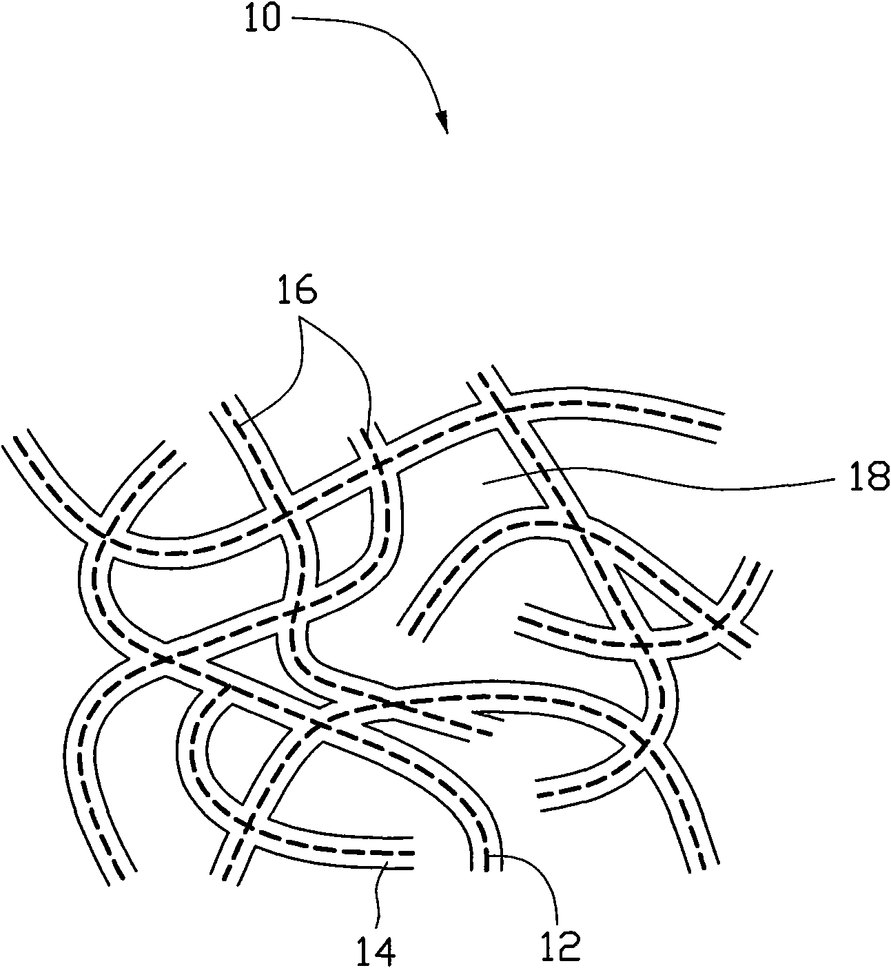
[0016] see figure 1 , the first embodiment of the present invention provides a thermoelectric conversion material 10 , which includes a carbon nanotube structure 16 and a conductive polymer layer 14 , wherein a dotted line represents a carbon nanotube 12 . The carbon nanotube structure 16 is formed by interconnecting multiple carbon nanotubes 12 . Adjacent carbon nanotubes 12 are connected to each other by van der Waals force. In the thermoelectric conversion material 10, the carbon nanotube structure 16 serves as a skeleton, and the conductive polymer layer 14 covers the surface of the carbon nanotubes 12 in the carbon nanotube structure 16, that is, the carbon nanotubes The structure 16 can support the conductive polymer layer 14 so that the conductive polymer layer 14 can be distributed on the surface of the carbon nanotub...


PUM

PropertyMeasurementUnit
sizeaaaaaaaaaa
thicknessaaaaaaaaaa
sizeaaaaaaaaaa

Abstract

The invention provides a flexible thermoelectric conversion material with high thermoelectric conversion efficiency. The thermoelectric conversion material comprises a carbon nano-tube structure and a conductive polymer layer. The carbon nano-tube structure comprises a plurality of carbon nano-tubes, and the conductive polymer layer is coated on the surface of the carbon nano-tubes.

Description

technical field [0001] The invention relates to a thermoelectric conversion material, in particular to a flexible thermoelectric conversion material. Background technique [0002] The thermoelectric effect (Thermoelectric Effect) means that when the temperature at both ends of the object is different (there is a temperature gradient inside the object), the carriers in the object will diffuse from the high temperature area to the low temperature area along the temperature gradient, resulting in the number of carriers in the low temperature area Gradually more than the high temperature region, thereby establishing a built-in electric field. The built-in electric field will force the carriers to perform a drift movement opposite to the diffusion movement, and finally the drift movement and the diffusion movement will balance, so that a constant potential difference exists at both ends of the object. The main parameter to measure the thermoelectric effect is Seebeck coefficient...

Claims


Application Information

Patent Timeline
Patent Type & Authority Applications(China)
IPC IPC(8): H01L35/24
CPCH01L35/26H01L35/22B82Y30/00H10N10/857H10N10/855
Inventor 孟垂舟刘长洪范守善
Owner TSINGHUA UNIV
Why Eureka
Try Eureka