Supercharge Your Innovation With Domain-Expert AI Agents!

Direct acting device

A direct-acting device and sliding piece technology, applied in the direction of transmission devices, electromechanical devices, electric components, etc., can solve the problems of large sliding resistance, complex structure, and large motor load of the driving device, so as to reduce the contact area and prevent large-scale , the effect of preventing dust intrusion

Active Publication Date: 2014-11-05
KURODA PRECISION INDS
View PDF8 Cites 0 Cited by
  • Summary
  • Abstract
  • Description
  • Claims
  • Application Information

AI Technical Summary

Problems solved by technology

[0017] In addition, in order to reduce the friction caused by the tension of the belt-shaped sealing ring, it is necessary to use rollers or low-friction materials between the belt-shaped sealing ring and the table, and the structure is relatively complicated.
[0018] In addition, there is a problem that the sliding resistance of the device itself is large due to the tension or friction of the belt-shaped seal ring, and the load on the motor of the driving device is large.

Method used


Image

  • Direct acting device
  • Direct acting device
  • Direct acting device

Examples


no. 1 approach

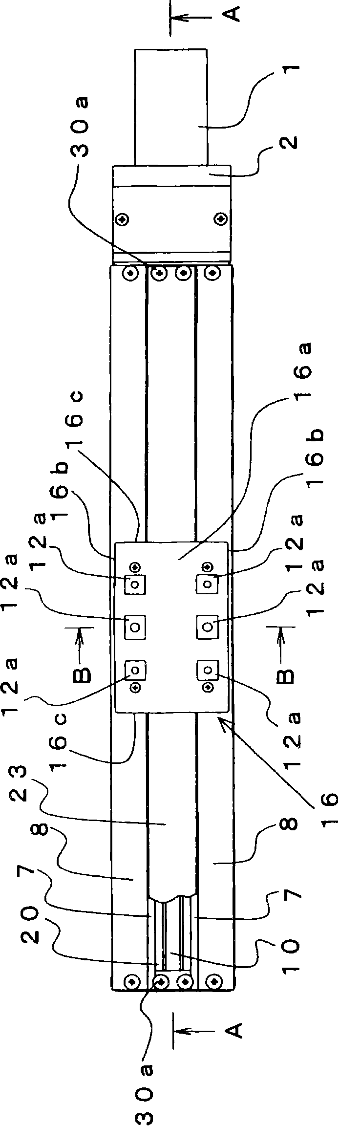
[0095] Figure 1 to Figure 13 A direct motion (direct motion) device according to the first embodiment of the present invention is shown.

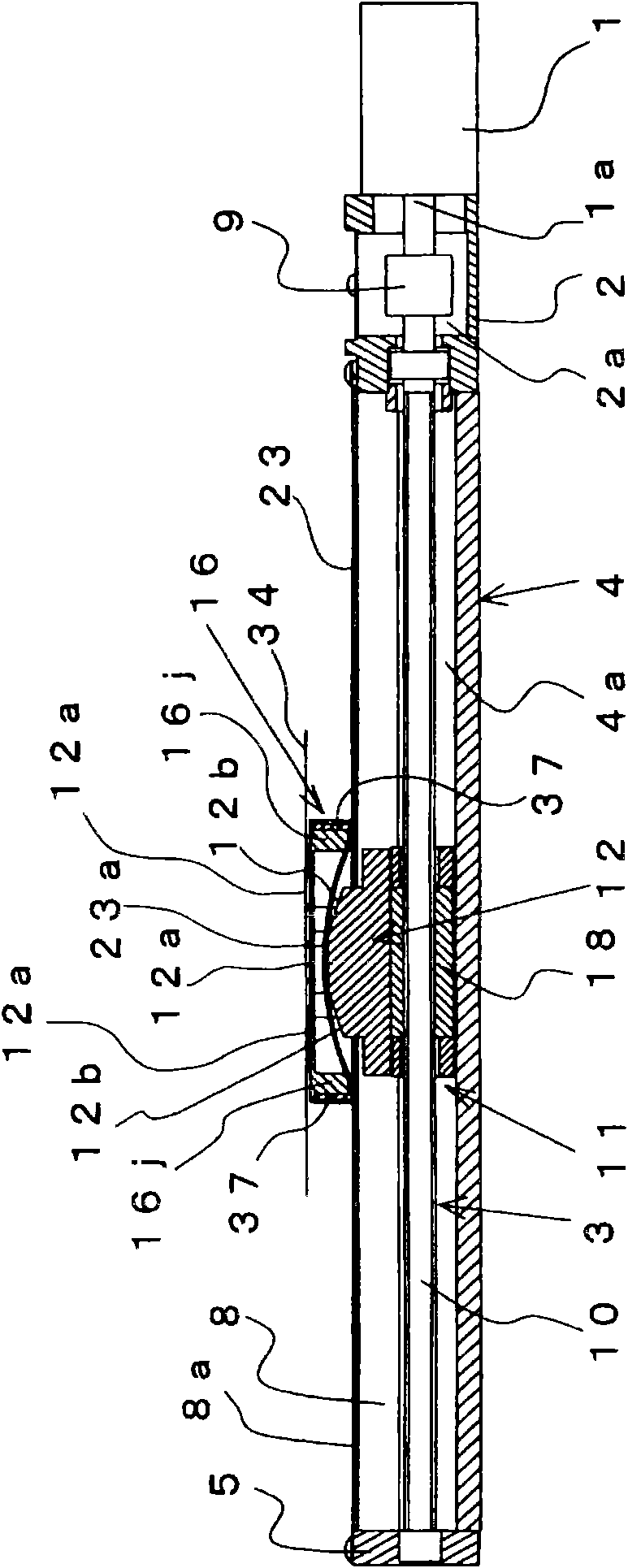
[0096] In the figure, 1 is a motor, 2 is a bracket which connects the ball screw 3 accommodated in the case 4, and the motor 1.

[0097] bracket 2 as figure 1 , figure 2 As shown, one end is connected to the motor 1 via a screw. In addition, the bracket 2 is provided with a hollow portion 2 a along the axial direction of the housing 4 , and a coupling portion 9 such as a coupling is provided in the hollow portion 2 a. The motor shaft 1 a is connected to the screw shaft 10 of the ball screw 3 at the connecting portion 9 .

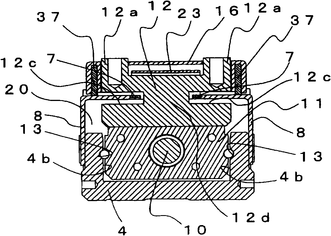
[0098] Shell 4 as figure 2 , image 3 As shown, an opening 20 is formed at the top in the axial direction along the moving direction of the slider 11 , that is, in the axial direction, and both ends in the axial direction are open. The recess 4a formed by the opening 20 is formed with a guide groove 13 for freel...

no. 2 approach

[0164] Figure 15 to Figure 18 表示本发明的第二实施方式涉及的直动装置。

[0165] 直动装置有为了增加工作台12的承载力而要求加长工作台12的长度的情况。

[0166] 但是,在第1实施方式涉及的直动装置中,如果想要增加工作台12的承载力,则工作台12如 image 3 所示,由于在长度方向上的两侧形成有侧盖8进入的凹部12c,所以在工作台12上形成有中间变细部12d,有可能工作台12的强度会下降。

[0167] 所以,在本实施方式中,通过加长工作台12的长度并增加中间变细部12d的截面积,能够增加工作台12的承载力。

[0168] 并且,如果使通过工作台12的上侧的带状的密封环带23的弯曲部23a变长,则仅在设置于工作台12的两端上的密封环带导引部16j处,带状的密封环带23的上表面遍及大范围向工作台盖16的内侧接触,有产生摩擦带来的滑动阻力、部件磨损的情况。

[0169] 所以,在本实施方式涉及的直动装置中,将滑动块11串联连结两个而配置,并且向设在工作台12的两端的密封环带导引部16j的中央位置的工作台盖16的内侧追加了密封环带导引部16k。

[0170] 其他结构与使用了1个滑动块11的第一实施方式涉及的直动装置是相同的。

[0171] 接着,对于在本实施方式中、优选地在工作台12的中央位置上设置密封环带导引部16k的理由进行说明。

[0172] a.为了防止滑动块11移动时的弯曲部23a的偏斜,需要将弯曲部23a均等地分为两个。因此,优选中间的密封环带导引部16k设在设于工作台12的两端的密封环带导引部16j的中央附近。

[0173] b.为了防止滑动块11移动时的弯曲部23a的偏斜,需要将弯曲部23a均等地分为两个。因此,优选中间的密封环带导引部16k的下表面处于比分为两个的弯曲部23a的顶点低的位置。

[0174] c.为了防止带状的密封环带23的两侧附近的劣化,中间的密封环带导引部16k的宽度优选的是与设在工作台12的两端的密封环带导引部16j的宽度相同,而相对于带状的密封环带23的宽度为50~80%。

[0175] 另外,密封环带导引部16k的前端部如 Figure 18 所示,与设在密封环带导引部16j的前端部的倒角16j′同样...


PUM


Abstract

A direct acting device is used for preventing dust from entering a shell. A band-shaped sealing ring belt has a certain length, so that the sealing ring belt can span an upper surface of a workbench to block an opening part, when the band-shaped sealing ring belt spans the upper surface of the workbench, a sealing ring belt guide part is contacted with the band-shaped sealing ring belt, so that the band-shaped sealing ring belt is bent to generate active force, and the active force makes the part of the band-shaped sealing ring belt, which does not span the upper surface of the workbench, fix towards a adhesion part, and when the band-shaped sealing ring belt spans the upper surface of the workbench, sliding plates block gaps between a workbench cover and an upper surface of a side cover and between the workbench cover and the band-shaped sealing ring belt.

Description

technical field [0001] The present invention relates to, for example, a linear motion device for linearly moving a slider through a ball screw or a hydraulic cylinder, and particularly relates to an anti-friction mechanism between a workbench connected to the slider and a housing housing the slider that operates the workbench. Improvement of the dust device. Background technique [0002] Conventionally, such a linear motion device has provided a strip-shaped sealing ring on the opening of the housing in order to prevent dust from entering the housing. [0003] However, since the table is connected to the slider, it has a structure in which the belt-shaped seal ring spans over the slider. Therefore, dust may intrude into the housing from the gap of the strip-shaped seal ring that floats up due to the action of the slider. [0004] In order to prevent this situation, for example, dare to set a small gap between the workbench and the casing, pressurize the inside of the casin...

Claims


Application Information

Patent Timeline
Patent Type & Authority Patents(China)
IPC IPC(8): H02K7/00F16H25/20F16J15/16F16J15/22
Inventor 大野敏明
Owner KURODA PRECISION INDS
Features
  • R&D
  • Intellectual Property
  • Life Sciences
  • Materials
  • Tech Scout
  • Unparalleled Data Quality
  • Higher Quality Content
  • 60% Fewer Hallucinations
Learn More